What is fluid structure interaction software?
Fluid structure interaction software models the two-way relationship between a fluid and a structure. It calculates how liquid or gas flow creates pressure and shear forces on a component, then how the component’s resulting movement or deformation changes the flow. Engineers use it for problems involving vibration, aeroelasticity, moving boundaries, pressure loading, and structural durability.
FSI is used where a fluid and a flexible or movable structure influence each other. Common applications include aircraft wings, turbine blades, valves, pumps, blood flow, offshore structures, pipes, and heat exchangers. It can help engineers identify resonance, excessive deflection, fatigue risks, flow-induced vibration, and performance changes before committing to fabrication or physical testing.
How does FSI software work?
Most FSI workflows couple a computational fluid dynamics model with a finite element structural model. The fluid solver calculates pressure, velocity, and temperature fields, while the structural solver calculates stress, displacement, and deformation. Data is exchanged between the two models over time until the coupled solution meets the selected convergence criteria and simulation objectives.
What is the difference between CFD and FSI?
Computational fluid dynamics, or CFD, focuses on fluid behavior such as velocity, pressure, turbulence, and heat transfer. FSI extends that analysis by accounting for structural movement or deformation caused by the fluid loads. CFD may be sufficient for rigid geometry, while FSI is more appropriate when structural response significantly changes the fluid domain or overall system behavior.
When is one-way versus two-way FSI appropriate?
One-way FSI transfers fluid loads to a structural model without feeding the structural deformation back into the fluid calculation. It is useful when deformation is small and does not materially alter flow. Two-way FSI continuously exchanges information between solvers and is needed when movement, vibration, or deformation substantially affects the flow field or loads.
What inputs are needed for an FSI analysis?
An FSI study typically needs accurate geometry, material properties, structural constraints, fluid properties, operating conditions, and interface definitions between fluid and structure. Depending on the problem, inputs may also include turbulence settings, thermal conditions, rotational speed, damping, contact conditions, load histories, and experimentally derived boundary conditions. Mesh quality and realistic assumptions strongly affect results.
Can gas turbine simulation replace dedicated FSI software?
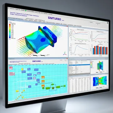
Gas turbine performance simulation and dedicated FSI analysis answer different engineering questions. A performance platform such as SimTurbo models engine architecture, thermodynamic cycles, steady-state and transient behavior, and controls. Dedicated FSI tools are generally used for detailed coupled fluid and structural response. Together, these approaches can support broader system-level and component-level engineering workflows.
How can engineers validate FSI or gas turbine simulation results?
Validation should compare simulation outputs with trusted analytical calculations, component data, test measurements, or published benchmark cases. Check boundary conditions, material properties, mesh independence, time-step sensitivity, and convergence before relying on results. For gas turbine work, SimTurbo reports validation against NASA Lewis Research Center J85-GE-21 engine test data, with reported accuracy within plus or minus 2%.