Engineers designing these machines face a familiar squeeze: aerodynamic performance goals often fight against mechanical and structural limits. A blade that extracts more work usually runs hotter, faster, or under more stress. Add long CFD and FEA iteration cycles, plus the challenge of proving a design against real test data before it's ever built, and the design cycle becomes a bottleneck.
This article walks through turbine fundamentals, the design process, stage types, analysis methods, and where optimization pays off most.
Key Takeaways
- Lock in stage performance with meanline sizing before moving into 3D blade design and CFD/FEA
- Impulse vs. reaction stage choice and blade stacking drive efficiency and structural stress
- Real-time, component-based simulation shortens iteration cycles compared to trial-and-error hardware testing
- Target secondary flow, tip-clearance leakage, and profile drag first when cutting aerodynamic losses
Understanding Axial Flow Turbines and Core Components
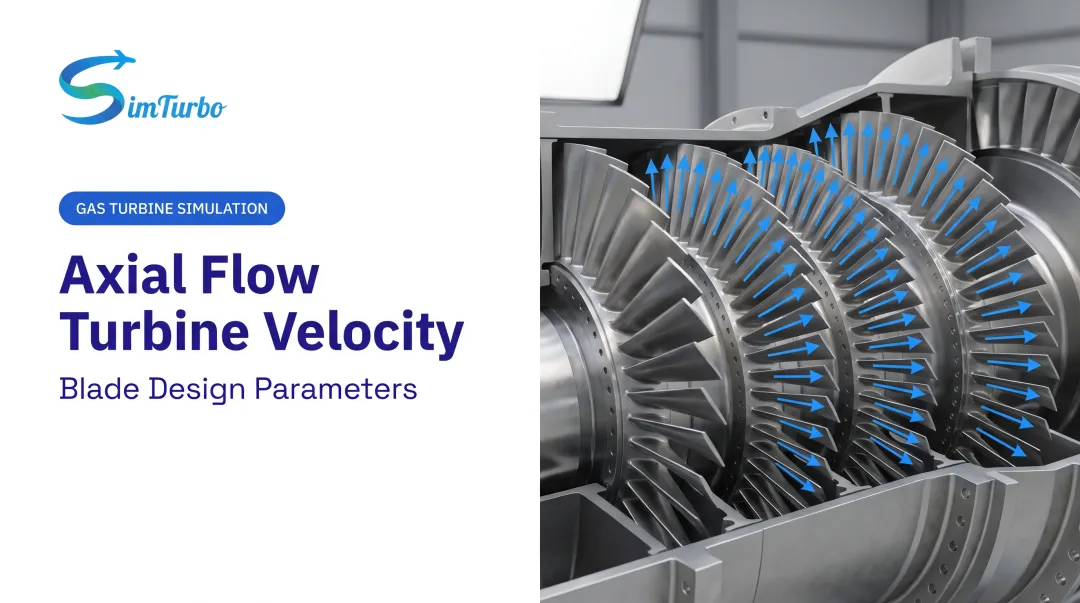
An axial flow turbine moves fluid parallel to the shaft axis. This contrasts with radial (centrifugal) turbines, where flow moves perpendicular to the shaft, and mixed-flow designs that blend both.
Axial turbines dominate high-flow, moderate-pressure-ratio applications like jet engines and steam power plants. Radial turbines suit smaller, higher-pressure-ratio duty cycles.
Core components include:
- Stator/nozzle vanes – accelerate and redirect flow, adding swirl without producing shaft work
- Rotor blades – extract work by reducing that swirl and converting momentum into torque
- Shaft – transmits rotor work to the driven load or compressor
- Casing – contains the flow path and manages clearances at the blade tips
The Language of Velocity Triangles
The Euler turbine equation ties specific work to the change in blade speed times swirl velocity. Velocity triangles, built from absolute velocity, blade speed, and relative velocity, expose incidence angles and exit swirl that determine how much work a stage actually delivers.
Theory and hardware don't always agree. A 1968 NASA single-stage axial turbine test measured total efficiency of 83.0% against a design target of 84.9%. Specific work landed at 10.78 Btu/lbm versus a designed 11.24 Btu/lbm, roughly a 4% shortfall. That gap is why analysis and validation matter as much as the initial calculation.
Turbines are generally grouped into impulse, reaction, and mixed (impulse-reaction) designs based on how pressure drop splits between stator and rotor — the subject of the next section.
The Axial Turbine Design Process
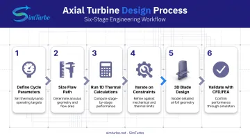
The design sequence follows a consistent path, regardless of application:
- Define cycle parameters – pressure ratio, mass flow, inlet temperature, and required work
- Size the flow path – root diameter, blade height, and heat-drop distribution across stages
- Run 1D thermal calculations – refine stage count and velocity ratios with simplified models
- Iterate on constraints – narrow the design space with reliability, manufacturability, and cost limits
- Move to 3D blade design – define spanwise swirl distribution and blade loading in detail
- Validate with CFD/FEA – confirm aerodynamic and structural performance before committing to hardware
Designers lean on meanline tools early because they can screen hundreds of geometry combinations before anyone opens a 3D solver.
A 2026 peer-reviewed study combining a meanline solver with genetic optimization and data mining completed its full four-stage turbine optimization in two days, versus months for traditional CFD-based methods. That's a single reported case, not a universal guarantee, but it illustrates why low-order tools still matter even in a CFD-heavy industry.
SimTurbo supports that early loop. Its component-based architecture lets engineers re-parameterize turbine and shaft blocks and immediately see the effect on cycle performance, rather than waiting on a full mesh regeneration for every iteration.
Stage Types: Impulse vs. Reaction Turbines
Stage type determines where pressure drop happens and how much work a single stage can extract.
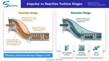
Impulse stages concentrate the pressure drop in the nozzle. The rotor ideally sees no static pressure change (degree of reaction R = 0). That setup allows high work extraction per stage. It suits cases where you need to absorb a large enthalpy drop compactly, such as a steam turbine's first stage.
Reaction stages share the pressure drop between stator and rotor. They can reach higher efficiency, but that advantage comes with trade-offs:
- Higher tip-leakage losses since the rotor now has a pressure gradient across it
- More complex sealing requirements
- Increased axial thrust on bearings
Compounding Strategies
Two classic compounding approaches solve different problems:
- Curtis (velocity-compounded) – absorbs a large first-stage enthalpy drop using high nozzle exit velocity across multiple rotor rows. Common in steam turbine control stages where compactness matters more than peak efficiency.
- Rateau (pressure-compounded) – spreads the drop across multiple simple impulse stages. More hardware, but generally better efficiency than a Curtis stage, according to ASME's mechanical drive steam turbine research.
Pick the approach based on enthalpy drop, size constraints, and cost tolerance.
Blade Stacking and Structural Considerations
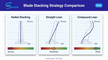
Blade stacking, meaning how the blade sections are arranged from hub to shroud, affects secondary flow near the endwalls. Options range from simple radial stacking to compound lean and controlled stacking strategies.
Why it matters:
- Radial stacking is the simplest but does little to manage endwall secondary flows
- Lean and bow can redistribute spanwise loading, weakening secondary flow strength near the hub or tip
- Stacking choices that raise efficiency often increase local Mach number and blade stress at the same time
A Cambridge cascade study tested identical blade sections with radial stacking, straight lean, and compound lean. Compound lean weakened secondary flows and downstream mixing, but the overall loss-coefficient change for that specific blade was minimal.
The lesson: redistributing loss isn't the same as reducing it. Stacking benefits are geometry- and Reynolds-number-dependent, not guaranteed.
Structural limits tighten the design space further. NASA's single-stage HPT study capped reaction at 43% because higher rotor axial load would overload bearings and cut durability. Aerodynamic gains always meet a structural ceiling.
Analysis Methods and Loss Optimization
Two analysis tracks run in parallel through detailed turbine design:
- CFD – resolves 3D flow, secondary vortices, and separation using structured meshes and turbulence models
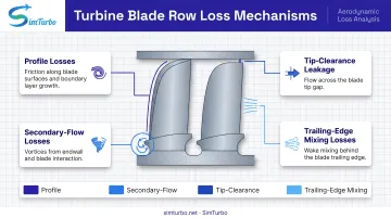
- FEA – validates blade stress, vibration modes, and thermal loading against material limits The four major loss mechanisms targeted in axial turbine optimization:
- Profile losses from blade surface boundary layers
- Secondary-flow losses near hub and shroud endwalls
- Tip-clearance leakage past rotor blade tips
- Trailing-edge mixing losses downstream of the blade row How well those losses are predicted depends on the model—and on how far you operate from the conditions it was built for.
Validation Accuracy Is Case-Specific
There's no single universal accuracy standard for turbine models. A 2023 ASME loss model calibrated against 228 CFD-evaluated cascades and nine real turbines achieved just 0.48% average stage-efficiency deviation at the design point. A separate 2024 off-design study found errors jumping to 18% once blade Mach number exceeded design values and flow separation appeared. The underlying loss model simply didn't capture that mismatch. Design-point percentages alone are not enough; real test data is the check that matters. SimTurbo's simulation platform was benchmarked against NASA Lewis Research Center test data for the J85-GE-21 single-spool turbojet, matching thrust, flow rate, temperature, and thrust-specific fuel consumption within ±2%. That result is engine-system performance validation, not turbulence-resolved CFD. It still gives engineers a real-time way to test velocity triangle and stage design assumptions against transient and steady-state behavior before committing to hardware.
Applications Across Industries
Design priorities shift depending on where the turbine operates:
| Application | Primary priority | Design implication |
|---|---|---|
| Steam control stages | Compactness, large enthalpy drop | Curtis staging accepts efficiency loss for size |
| Aerospace HPT | High work density, cooling, weight | Fewer stages raise per-stage loading and stress |
| Aerospace LPT | Efficiency at low Reynolds number | More stages, lower individual loading |
| Marine/industrial | Reliability across a broad operating map | Off-design performance matters as much as peak efficiency |
Fewer stages mean less weight and lower part count, but higher loading per stage — a trade-off that shows up in every one of these sectors.
Those sector-specific trade-offs are exactly what you want to pressure-test before committing hardware. Engineers use SimTurbo to try architecture and control choices against the priorities above; universities run the same platform under discounted licensing for propulsion courses, capstone projects, and gas turbine curricula.
Frequently Asked Questions
What are three types of turbine design?
Turbines are commonly grouped as impulse, reaction, and mixed (impulse-reaction) designs. Impulse stages drop pressure in the nozzle; reaction stages share that drop between stator and rotor; mixed designs sit between those extremes.
Is the Kaplan turbine an axial flow turbine?
Yes. The Kaplan turbine is an axial-flow hydraulic turbine used in low-head, high-flow hydropower applications. It differs from gas and steam axial turbines mainly in working fluid and operating conditions.
What is the difference between axial flow and centrifugal (radial) turbines?
Axial turbines move fluid parallel to the shaft; radial turbines move fluid perpendicular to it. Axial designs suit high-flow, moderate-pressure applications, while radial designs fit smaller, higher-pressure-ratio duty cycles.
What is the degree of reaction in a turbine stage?
Degree of reaction is the ratio of rotor static enthalpy drop to total stage enthalpy drop. Common design values are 0 for impulse stages and 0.5 for balanced reaction stages.
How do engineers validate axial turbine designs before building hardware?
Engineers combine CFD, FEA, and thermodynamic cycle simulation checked against real test data. Tools such as SimTurbo help catch architecture and matching issues before hardware builds, cutting prototyping cost and risk.