A PID pressure controller is a specialized control device that uses Proportional-Integral-Derivative algorithms to automatically regulate pressure in industrial systems. It continuously compares measured pressure against a desired setpoint and calculates the necessary adjustments to control valves or regulators, ensuring stable operation across changing conditions.
This article explores how PID pressure controllers work, the types of implementations available (pneumatic, electronic analog, and digital), real-world applications across industries, tuning strategies for optimal performance, and key selection criteria to match controllers with your process requirements.
Key Takeaways
- PID pressure controllers hold setpoints with P (error response), I (drift elimination), and D (oscillation dampening)
- Pneumatic, electronic analog, and digital formats suit different environments and integration needs
- Chemical processing, HVAC, manufacturing, and power generation use them for safety and efficiency
- Tune Kp, Ki, and Kd with manual methods, Ziegler-Nichols, or automated software for stable control
- Choose by accuracy, response time, environment, protocols, and total cost of ownership
Understanding PID Control Fundamentals
How PID Controllers Work
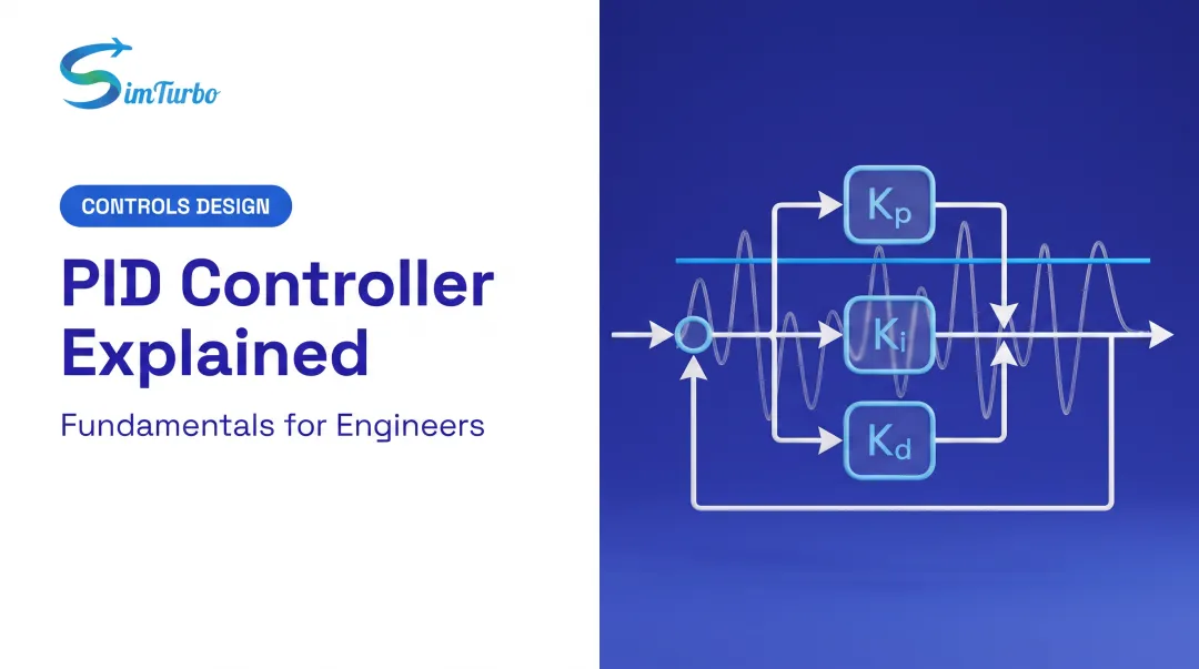
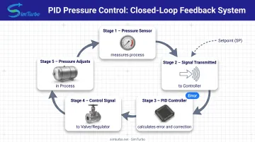
A PID pressure controller operates as a closed-loop feedback system. The pressure sensor continuously measures the process variable (PV) and transmits it to the controller, which compares it against the setpoint (SP). The difference, called the error signal, drives the controller's output calculation.
The control output adjusts a control valve or pressure regulator based on the weighted sum of three terms:
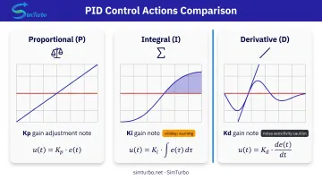
- Proportional (P): responds to the magnitude of the current error
- Integral (I): accumulates past errors over time
- Derivative (D): predicts future error based on the rate of change
This feedback cycle repeats continuously, with the controller modulating the actuator position to minimize error and maintain the desired pressure.
The Three Control Actions Explained
Proportional (P) Action:
Proportional control produces an output directly proportional to the current error. A larger proportional gain (Kp) speeds response, but excessive gain can cause overshoot and oscillation, as noted in NI's PID theory overview.
Integral (I) Action:
Integral action accumulates past errors to eliminate steady-state offset: a persistent gap between setpoint and measured pressure that proportional-only control cannot remove. The integral gain (Ki) determines how quickly accumulated error is corrected.
A common problem is integral windup: when the control valve saturates (reaches its physical limit), the integral term continues to accumulate error, causing overshoot when conditions change. Prevention methods include back-calculation, clamping, and conditional integration (NI).
Derivative (D) Action:
Derivative action responds to the rate of change of the error, providing a predictive element that dampens oscillations and improves stability. The derivative gain (Kd) adjusts how aggressively the controller reacts to rapid changes.
However, derivative response is highly sensitive to measurement noise, and most practical systems use very small derivative time. In noisy pressure-sensor applications, derivative action is often reduced or eliminated entirely to prevent erratic control output.
Control Loop Components
Every PID pressure control loop includes four essential components:
- Pressure sensor/transmitter: Measures process pressure and converts it to a standard signal (4-20 mA, 0-10 VDC, or digital)
- PID controller: Receives the sensor signal, calculates error, applies the PID algorithm, and generates a control output
- Control valve or pressure regulator: Adjusts flow or valve position in response to the controller output
- Process being controlled: The vessel, pipeline, or system where pressure must be maintained
Signal flow: Sensor measures pressure → transmits to controller → controller calculates correction → actuates control element → pressure adjusts → cycle repeats.
Why PID for Pressure Control?
Simpler control methods fall short in dynamic pressure applications. On-off control causes constant cycling and valve wear, while proportional-only control leaves a steady-state offset between setpoint and actual pressure.
PID removes that offset through integral action, and derivative action improves disturbance response without excessive overshoot.
Pressure control presents unique challenges:
- System inertia and dead time delay response
- Nonlinear valve characteristics alter loop gain at different positions
- Load disturbances (flow changes, temperature shifts) require continuous correction
- Compressibility effects in gas systems create storage dynamics that complicate control
PID's three-term structure is built for that mix of delay, nonlinearity, and disturbance—so the loop can stay fast without giving up setpoint accuracy.
PID Pressure Controller Implementation Types
PID pressure controllers are built in three main forms: pneumatic, electronic analog, and digital. The right choice depends on hazardous-area needs, response speed, and how tightly you must integrate with plant systems.
Pneumatic PID Controllers
Pneumatic controllers use air pressure signals to represent setpoint, process variable, and output. Mechanisms include force-balance and motion-balance designs using bellows, nozzles, and flappers. The industry-standard signal range is 3-15 psi.
Advantages:
- Intrinsically safe for hazardous locations (no electrical sparks)
- Simple maintenance with mechanical components
- No electrical power required
- Proven reliability in explosive or corrosive environments
Limitations:
- Slower response than electronic controllers
- Limited integration with modern digital systems
- Requires clean, dry compressed air supply
Example: Fisher 4195KCF compares process pressure to an adjustable setpoint and sends a pneumatic signal to the final element.
Electronic Analog PID Controllers
Analog controllers implement P, I, and D functions using operational amplifier circuits with resistors, capacitors, and amplifiers. Continuous analog signals eliminate sampling delays present in digital systems.
Advantages:
- Faster response than pneumatic
- Easy integration with electronic instrumentation
- Standard 4-20 mA current loop signals
- No aliasing or quantization effects
Limitations:
- Requires electrical power and explosion-proof enclosures in hazardous areas
- Susceptible to electrical noise without proper grounding and shielding
- Fixed functionality compared to software-based systems
Digital/Microcontroller PID Controllers
Digital controllers execute PID algorithms in software on microcontrollers, PLCs, or dedicated digital platforms. The discrete-time algorithm samples the process variable at regular intervals and calculates the control output numerically.
Advantages:
- Flexible tuning with adjustable parameters via software
- Adaptive control and gain scheduling possible
- Data logging, alarm functions, and remote monitoring
- Multiple control loops in one device
- Auto-tuning algorithms simplify commissioning
Modern features:
- Setpoint ramping for gradual pressure changes
- Bumpless transfer between manual and automatic modes
- Communication protocols for SCADA/DCS integration
- Performance diagnostics and trending
Examples:
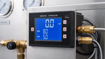
- Alicat PCD dual-valve controller: 1–3,000 psi, 30 ms response, multi-protocol industrial comms
- Bronkhorst EL-PRESS: up to 400 bar, ±0.5% FS accuracy, 2 ms sensor response, fieldbus/Ethernet options
Tuning PID Pressure Controllers
Why Tuning Matters
Default PID parameters rarely deliver optimal performance. Poor tuning causes:
- Slow response to setpoint changes
- Excessive overshoot or undershoot
- Sustained oscillation around the setpoint
- Instability under disturbances
Tuning involves trade-offs:
- Fast response vs. stability: Aggressive gains speed response but reduce robustness
- Disturbance rejection vs. setpoint tracking: Different gain combinations optimize for external disturbances versus setpoint changes
Common Tuning Methods
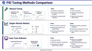
Manual Tuning
A step-by-step process where an experienced operator adjusts Kp, Ki, and Kd while observing system response:
- Set Ki and Kd to zero; increase Kp until the system oscillates with acceptable overshoot
- Increase Ki to eliminate steady-state offset, monitoring for overshoot and recovery time
- Add Kd cautiously to dampen oscillations, watching for noise amplification
Ziegler-Nichols Method
A classical approach that provides structured tuning formulas:
- Set Ki and Kd to zero; increase Kp until the system exhibits sustained oscillation
- Record the ultimate gain (Ku) and oscillation period (Pu)
- Calculate PID parameters using established formulas: Kc = 0.6Ku, Ti = Pu/2, Td = Pu/8 (LibreTexts classical PID tuning methods)
Caution: Testing to sustained oscillation can enter unstable regions and should be performed carefully.
Software-Based Auto-Tuning
Modern controllers run automated step tests and calculate starting gains for you. Model-based tools such as the MathWorks PID Tuner adjust gains from linearized models or estimated frequency responses, balancing robustness and performance. Treat auto-tune results as a baseline—verify them under real load, noise, and disturbance conditions before you lock settings in.
Practical Tuning Considerations
Pressure-specific challenges include:
- Valve hysteresis and stiction: Deadband and static friction make the valve stick until the signal is large enough to move it. Emerson targets total valve-assembly deadband of 1% or less for best variability reduction.
- Dead time: Delays between valve movement and pressure change slow loop response
- Nonlinear process gain: Equal-percentage valves change loop gain at different operating points
Best practices
- Start with conservative settings and incrementally improve
- Document baseline performance (settling time, overshoot, steady-state error) before changes
- Reduce or eliminate derivative action if pressure-sensor noise creates erratic output
- Consider valve positioners to improve actuator response and reduce deadband
Industrial Applications of PID Pressure Controllers
PID pressure controllers show up wherever stable pressure protects safety, product quality, or energy efficiency. The same feedback loop scales from plant reactors to gas turbine fuel and bleed systems.
Chemical and Process Industries
In chemical reactors, tight pressure control protects against rupture and keeps reaction rates on target. Underpressure slows the reaction and can open the door to contamination.
Distillation depends on stable pressure for separation efficiency and product quality. Pressure swings shift component boiling points, disturb vapor-liquid equilibrium, and cut separation performance.
HVAC and Building Automation
Common PID pressure loops in buildings include:
- Zone, duct static, and building pressurization control in pneumatic systems
- Refrigerant pressure control on chillers for efficiency
- Steam pressure regulation on boilers for safe, steady heat output
Manufacturing and Production
On the plant floor, pressure loops protect both tool consistency and formed-part quality:
- Pneumatic tools and cylinders: steady air pressure for repeatable tool performance and controlled actuator speed
- Hydraulic presses, injection molding, and metal forming: accurate force and cycle-to-cycle repeatability
Aerospace and Power Generation
Gas turbines need precise pressure control on fuel systems, compressor bleed valves, and combustion. Surge margin, the buffer between the compressor operating point and the surge line, has to stay intact to avoid compressor stall.
Control engineers often prove these loops in simulation before hardware runs. With SimTurbo, teams can tune PID pressure parameters, exercise startup and fault cases, and cut commissioning risk without tying up an engine test cell.
Selecting the Right PID Pressure Controller
Application Requirements Analysis
Define key specifications before selecting a controller:
- Pressure range: Maximum and minimum operating pressures
- Accuracy requirements: Expressed as ±% of span or absolute units (e.g., ±0.5% FS or ±0.1 psi)
- Response time: Time constant or settling time needed to reach setpoint after a disturbance
Match those specs to how the process actually behaves:
- Fluid type: Gas, liquid, or steam (each has different compressibility and response dynamics)
- Temperature range: High temperatures may require specialized sensors and electronics
- Flow rate variations: Large flow changes affect pressure dynamics and disturbance magnitude
- Disturbance frequency: Frequent disturbances require faster integral action
Environmental and Integration Factors
Once the loop requirements are clear, check whether the install site and plant network constrain the hardware you can use.
Installation environment:
- Hazardous area classification: Intrinsically safe pneumatic controllers or explosion-proof enclosures for electronic types
- Temperature extremes: Electronics may require temperature compensation or environmental enclosures
- Vibration and humidity: Ruggedized designs for harsh industrial settings
Integration Needs:
Most modern plants need the controller to talk to SCADA or DCS. Common options include Modbus RTU/TCP, PROFIBUS, EtherCAT, PROFINET, EtherNet/IP, DeviceNet, and IO-Link—pick what your existing network already supports.
Performance vs. Cost Trade-offs
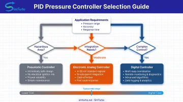
With requirements and environment defined, choose the implementation that fits complexity—and budget:
- Pneumatic: Best for hazardous locations, simple single-loop applications, and environments where electrical power is unavailable
- Electronic analog: Suitable for moderate-speed applications requiring electronic integration without digital complexity
- Digital: Ideal for complex multi-loop systems requiring data logging, remote monitoring, adaptive control, or integration with plant networks
Cost considerations:
Digital pressure controller pricing varies widely by range, accuracy, and I/O. Treat sticker price as only one line in total cost of ownership:
- Initial purchase price
- Installation and commissioning labor
- Calibration and maintenance
- Energy consumption (electrical power or compressed air)
- Eventual replacement and disposal
For gas turbine and other high-stakes pressure loops, prove the PID strategy in simulation before you freeze hardware and commissioning plans. That step surfaces gain, actuator, and disturbance issues early—when changes still cost little.
Common Challenges and Solutions in PID Pressure Control
Integral Windup and Prevention
When a control valve hits its physical limit (fully open or closed), controller output saturates. If error persists, the integral term keeps accumulating. When the error later changes sign, that stored integral value drives excessive overshoot and slow recovery.
Common anti-windup approaches include:
- Back-calculation: Feed saturation error through a tracking loop to unwind the integrator
- Clamping / conditional integration: Stop integral accumulation while the output is saturated
- Tracking: Feed the actual actuator output back into the controller
These methods are standard in industrial PID implementations and are well documented in resources such as MathWorks’ anti-windup PID examples.
Valve Nonlinearity and Deadband
Equal-percentage valves deliver equal percentage flow changes for equal travel increments. Linear valves deliver equal flow increments instead. That difference changes loop gain across the operating range—equal-percentage valves usually show lower gain near closed and higher gain when open—so a single PID tuning can feel sluggish in one region and aggressive in another.
Deadband is controller-output travel that produces no process-variable change after a direction reversal. Static friction (stiction) is a major cause, and the result is limit-cycle oscillation and poor control quality.
Practical fixes:
- Install valve positioners to tighten response and reduce deadband
- Raise proportional gain cautiously to overcome stiction, while watching stability margins
- Specify low-friction valves with about 1% deadband or less
Measurement Noise and Filtering
Pressure-sensor noise is amplified by the derivative term, which reacts to rate of change. Random spikes create large derivative kicks, erratic valve motion, and instability.
Ways to manage noisy pressure signals:
- Apply low-pass filtering on the process variable before derivative action
- Reduce or remove derivative action in noisy loops
- Upgrade to higher-quality pressure transmitters with a better signal-to-noise ratio
Filtering adds lag, so you may need slightly slower PID tuning to keep the loop stable.
Simulation and Testing of Pressure Control Systems
Why Simulate Before Implementation
Virtual testing helps you:
- Validate control strategy before hardware purchase
- Optimize PID parameters without disrupting production
- Identify potential stability issues in a safe environment
- Reduce commissioning time and risk
Virtual prototyping allows engineers to test control logic against dynamic process models before connecting to physical equipment.
Simulation Tools and Approaches
First-Order Plus Dead Time (FOPDT) Models:
FOPDT models approximate pressure processes using three parameters:
- Process gain (K): Change in pressure per unit change in valve position
- Time constant (τ): How quickly the process responds
- Dead time (θ): Delay between valve movement and pressure change
These compact models provide initial controller tuning estimates from step-response data.
Industry-Specific Simulation:
Specialized simulation environments exist for specific industries. Engineers designing gas turbine engine control systems can use SimTurbo to model full engine dynamics, including pressure control loops, fuel systems, and compressor bleed valve control with built-in PID components.
That setup supports testing control parameters across operating scenarios such as startup, slam-acceleration, and surge-margin management before engine tests.
Hardware-in-the-Loop Testing
Hardware-in-the-loop (HIL) connects a physical controller to a simulated process running in real time. The controller receives sensor signals from the simulation and sends control outputs back, forming a closed loop with virtual plant dynamics.
HIL testing supports:
- Realistic checks of actual control hardware without a physical plant
- Operator training on real control interfaces
- Fault scenario testing without production risk
- Procedure validation before commissioning
Future Trends in PID Pressure Control
Adaptive and Self-Tuning Controllers
Gain scheduling automatically adjusts PID parameters based on operating point to handle nonlinear process behavior. For pressure loops, gains can shift with pressure level or flow rate so performance stays consistent across the range—see MathWorks' gain-scheduled PID guidance.
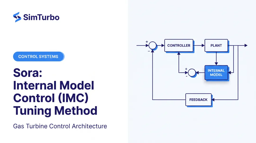
Model-based adaptive control keeps an internal process model current as the plant changes (fouling, valve wear, temperature drift), then retunes PID parameters automatically so the loop stays near optimal without manual retuning.
AI and Machine Learning Integration
Machine learning algorithms can analyze historical performance data to optimize PID parameters. By learning from thousands of control cycles, AI systems identify patterns that human operators might miss and recommend tuning adjustments.
Pressure-specific published case studies are still limited, but ML-assisted tuning is already a practical fit for multivariable or time-varying pressure processes where fixed Ziegler–Nichols or trial-and-error tuning falls short.
IoT and Cloud-Connected Controllers
Modern digital controllers support remote monitoring and cloud connectivity over common industrial protocols such as EtherCAT, EtherNet/IP, Modbus TCP, PROFINET, and IO-Link.
Potential benefits:
- Centralized tuning databases shared across multiple sites
- Performance benchmarking to flag underperforming loops
- Predictive maintenance from control metrics (rising variance, longer settling times)
- Automatic firmware updates and security patches
Connected pressure loops can feed plant-wide optimizers and analytics with live performance data, not only local setpoint tracking.
Frequently Asked Questions
What is a PID pressure controller and what is its main purpose?
A PID pressure controller automatically holds a pressure setpoint by adjusting a valve or regulator. It combines proportional (current error), integral (removes offset), and derivative (damps oscillation) action to close the gap between measured and target pressure.
How much does a PID pressure controller cost?
Costs vary by type and features: pneumatic units often run $200–$800, electronic analog $300–$1,500, and digital $800–$5,000+. The Alicat PCD Series, for example, starts at $1,605. Accuracy, range, communications, and hazardous-area ratings drive price.
What is the difference between a PLC and a PID pressure controller?
A PLC is a general-purpose industrial computer that can run many logic and control tasks, including PID. A PID pressure controller is a dedicated single-loop device for pressure regulation. PLCs win on multi-variable flexibility; dedicated PID controllers are simpler, often cheaper for one loop, and can respond faster in hardware.
Can PID controllers be used for other variables besides pressure?
Yes. The same PID algorithm works for temperature, flow, level, pH, and other variables; only the sensor and tuning change. Temperature loops, for example, are usually slower than pressure and need different Ki and Kd settings.
What happens if PID tuning is incorrect?
Bad tuning hurts performance: excess proportional gain causes oscillation; too little slows response. Weak integral leaves offset; too much causes overshoot. Poor derivative amplifies noise. You get wasted energy, lower product quality, and faster valve wear.
How often should PID controllers be retuned?
Retune when the process changes (new equipment, product switches, seasonal shifts), after controller or valve work, or when settling time, overshoot, or steady-state error gets worse. Baseline your metrics so drift is obvious. Stable loops may need only annual checks; dynamic or aging processes need more frequent attention.