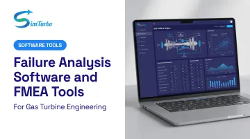
Modern failure analysis is shifting from reactive root-cause investigations to proactive Failure Mode and Effects Analysis (FMEA), and specialized software now bridges the gap between risk identification and prevention. This guide defines FMEA, explores its main variants (DFMEA, PFMEA, SFMEA, and FMECA), walks through the industry-standard seven-step process, and provides practical criteria for selecting FMEA tools that integrate with simulation, requirements management, and product lifecycle workflows.
Key Takeaways
- FMEA spots failure modes early and ranks corrective actions before production starts
- AIAG-VDA Action Priority tables replace pure RPN so high-severity risks stay visible
- Modern FMEA tools link failure modes to requirements and flag design-change impacts automatically
- Cross-functional input plus milestone updates keep FMEA accurate across the product lifecycle
- Simulation validates Occurrence and Detection ratings with virtual failure scenarios before physical tests
What Is FMEA and Why It Matters in Product Development
FMEA is a systematic, step-by-step method to identify and prioritize possible failures in a product, process, or system. Unlike reactive root-cause analysis, which investigates failures after they occur, FMEA is done during design and process planning, when changes are still inexpensive and schedule impact stays low.
Core Concepts
Failure mode describes the specific way a component, process, or system can fail. Examples include bearing seizure in a gas turbine, software timeout in an avionics controller, or weld fracture in a pressure vessel.
Effects analysis maps the downstream consequences of each failure mode on subsystems, end users, and safety. For instance, a bearing failure may cause loss of rotor support, leading to turbine blade rub, engine fire, and ultimately aircraft loss.
The Three Risk Factors
FMEA scoring rests on three dimensions:
- Severity (S): How serious is the consequence? Rated 1 to 10, from insignificant to catastrophic
- Occurrence (O): How likely is the failure? Rated 1 to 10, from remote to nearly certain
- Detection (D): How well do current controls catch it before it reaches the customer? Rated 1 to 10, from almost certain detection to almost certain escape
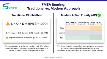
Traditional practice multiplied S × O × D to produce a Risk Priority Number (RPN) ranging from 1 to 1,000. Modern standards now use Action Priority (AP) tables that prioritize severity first, avoiding scenarios where high-severity failures are buried by favorable occurrence or detection scores.
Industry Context and Mandates
FMEA is required or strongly recommended across regulated industries:
- Automotive: SAE J1739:2021 covers DFMEA, FMEA-MSR, and PFMEA; Stellantis CSR mandates supplier DFMEA/PFMEA
- Aerospace: SAE ARP4761 guides civil aircraft safety assessment
- Medical devices: A 2025 study finds FMEA the most-used tool, though not enough alone for full ISO 14971:2019 compliance
- Power systems: IEC 61508 uses FMEA to evaluate component failure modes within functional safety analysis
No universal ROI figure exists for early FMEA, but the cost curve is well known: weaknesses caught in design stay cheap to fix; failures that reach the field do not.
Types of FMEA: Design, Process, System, and Criticality Analysis
Design FMEA (DFMEA)
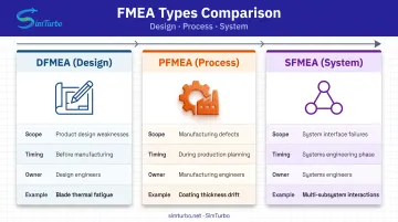
DFMEA examines potential failures in the product design itself (component functions, material properties, tolerances, and interfaces) before manufacturing begins. It focuses on inherent design weaknesses without assuming process controls exist.
Gas turbine examples:
- Turbine blade thermal fatigue due to sustained high exhaust gas temperature
- Compressor surge triggered by off-design mass flow or back-pressure spikes
- Bearing fit tolerance leading to fretting wear and eventual seizure
DFMEA is typically owned by product and design engineers and feeds critical requirements into subsequent process planning.
Process FMEA (PFMEA)
PFMEA analyzes how manufacturing or assembly processes could introduce defects, assuming the design itself is sound. It follows DFMEA in the workflow and focuses on production risks.
Engineers often use the 6M framework (Man, Method, Material, Machine, Measurement, Environment) to brainstorm process failure causes. However, this is a mnemonic tool, not a mandated AIAG-VDA step.
Gas turbine process examples:
- Blade coating thickness drift from spray-parameter variation
- Rotor unbalance introduced during assembly stack-up
- Sensor miscalibration during end-of-line test setup
PFMEA outputs feed the Control Plan, which defines inspections, process parameters, and corrective actions for production. Frontline operator input matters here: production teams often know how equipment actually fails.
System FMEA (SFMEA)
SFMEA analyzes failures at system and subsystem interfaces: failures that individual component FMEAs cannot catch. For example, a fuel control system and turbine temperature sensor might interact to cause uncommanded acceleration, even though each subsystem passes its own DFMEA.
SFMEA is part of systems engineering practice and is common for complex, multi-discipline products such as gas turbines, avionics, and electric powertrains. SAE published an updated SFMEA standard (SAE1025) in January 2026, though detailed definitions require the licensed document.
FMECA (Failure Mode, Effects, and Criticality Analysis)
FMECA extends FMEA by adding a criticality ranking based on severity and probability, often used in military and aerospace programs per MIL-STD-1629A. Teams use that ranking to prioritize the highest-risk failure modes. Exact criticality categories and calculation methods are defined in the standard.
How to Perform FMEA: A 7-Step Process
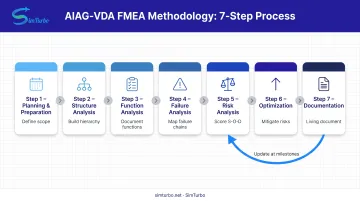
The AIAG-VDA FMEA Handbook defines a seven-step structured approach:
- Planning and Preparation
- Structure Analysis
- Function Analysis
- Failure Analysis
- Risk Analysis
- Optimization
- Documentation of Results
Step 1–2: Planning and Structure Analysis
Step 1 establishes scope, boundaries, and project intent. Teams:
- Define what will and won't be analyzed
- Identify required expertise
- Schedule FMEA reviews aligned with phase gates
Step 2 builds structure trees (system → subsystem → component) and boundary diagrams to visualize the analysis scope. That decomposition shows where interfaces exist and which teams own each element.
Step 3–4: Function and Failure Analysis
Step 3 documents each element's intended function. For example: "Compressor section increases air pressure from 1 bar to 10 bar at design flow rate."
Step 4 builds the failure chain:
- Function → Failure Mode → Effect → Cause
Assess effects at the next higher level and on the end user. A bearing failure is not only "loss of rotor support." It can cascade to turbine blade rub, secondary damage, and loss of engine function.
Step 5: Risk Analysis and AP Scoring
Severity, Occurrence, and Detection are rated on 1–10 scales. Traditional RPN multiplies all three, producing a score between 1 and 1,000.
RPN can still bury safety-critical failures. A severity-10, occurrence-2, detection-3 case yields RPN = 60, lower than a severity-5, occurrence-6, detection-4 case (RPN = 120).
The AIAG-VDA shift to Action Priority (AP) tables prioritizes severity first, assigning High/Medium/Low action categories based on the S/O/D combination rather than a single product score. This ensures high-severity failures receive attention regardless of occurrence or detection ratings.
Example comparison:
| Failure Mode | S | O | D | RPN | AP Priority |
|---|---|---|---|---|---|
| Turbine blade fracture | 10 | 2 | 3 | 60 | High |
| Weld porosity | 5 | 6 | 4 | 120 | Medium |
Under RPN alone, the blade fracture would receive lower priority. AP corrects this by elevating any severity-10 failure to High priority.
Step 6–7: Optimization and Documentation
Step 6 applies the mitigation hierarchy:
- Eliminate the failure effect (design it out)
- Reduce occurrence (improve robustness)
- Improve detection (add monitoring or inspection)
Each action must have an owner, due date, and verification evidence. Teams re-score after implementation to confirm risk reduction.
Step 7 produces the final FMEA report. Treat it as a living document: update it at phase gates, design changes, and field failures so risk controls stay current.
Choosing FMEA Software: Key Selection Criteria
Before you standardize on a stack, pick the right class of tool for how your team works:
- Excel or shared spreadsheets for lightweight, ad hoc FMEA
- Standalone FMEA tools (such as Relyence or PQ-FMEA)
- Integrated PLM/ALM platforms (Jama Connect, PTC Windchill)
- Domain-specific simulation environments that validate failure scenarios
Criterion 1: Traceability to Requirements and Design
The primary weakness of Excel-based FMEA is that failure modes become "orphaned" when upstream requirements or designs change. Modern FMEA software links each failure mode to the requirement or component it analyzes, so impact analysis updates when those inputs change.
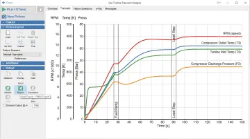
Simulation tools can go further. For gas turbine work, platforms like SimTurbo model transient scenarios (compressor surge, sensor failures, thermal spikes) and export time-series data—RPM, exhaust gas temperature, thrust, fuel consumption—to CSV or Excel for post-processing.
Engineers can then pressure-test Occurrence and Detection ratings with virtual failures before hardware runs. Not every simulator ships a formal FMEA-rating workflow, so confirm how export data maps into your FMEA tool.
Criterion 2: Collaboration and Cross-Functional Access
Effective FMEA requires real-time input from design engineers, manufacturing engineers, quality teams, and operators. If the team cannot work in the same record, advanced analytics will not save the study. Prioritize platforms that offer:
- Role-based access for design, manufacturing, quality, and operations
- Concurrent editing so reviews do not serialize on one owner
- Comment threads tied to specific failure modes or controls
Criterion 3: Compliance and Audit Readiness
Regulated industries (automotive, aerospace, medical devices) need audit-ready controls, not just worksheets. Confirm support for:
- Automated revision history and electronic signatures
- Report output aligned with AIAG-VDA, SAE J1739, ISO 26262, or FDA 21 CFR Part 11
- The exact standard version and deployment model your auditors require
Common FMEA Pitfalls and How to Avoid Them
FMEA only protects you if it stays current and honest. These three pitfalls show up often in design and process work—and each has a clear fix.
Pitfall 1: Treating FMEA as a One-Time Design Review Checkbox
The "file and forget" problem is widespread: teams complete FMEA to satisfy a phase gate, then never update it when requirements, designs, or field data change. The result is a stale document that provides false confidence.
Solution: Treat FMEA as a living record, not a gate artifact:
- Update at every major milestone: design change, process change, or production failure
- Connect FMEA software to change-management workflows so revisions are triggered, not optional
- Follow SAE J1739:2021 on change management across the full FMEA lifecycle
Pitfall 2: Ignoring Severity in Favor of RPN
Teams sometimes manipulate Occurrence or Detection scores to keep RPN below a threshold, claiming a detection method is "foolproof" so Detection drops from 8 to 3 with no physical validation. That practice can bury safety-critical failures.
Solution: Adopt AIAG-VDA Action Priority (AP) tables, which prioritize severity first. AP uses the S/O/D combination rather than a single product score, ensuring high-severity risks receive attention regardless of other factors.
Pitfall 3: Missing the Voice of the Operator and Field Engineer
Engineers who write FMEAs often lack firsthand knowledge of how equipment actually fails in production or service. Stellantis requires a Reverse PFMEA process to identify new modes or verify existing modes on the shop floor, with activities scheduled and tracked.
Solution: Involve operators, technicians, and field service teams in failure brainstorming sessions. Their input often uncovers modes that design engineers would never anticipate.
Frequently Asked Questions
Which software is used for FMEA?
Teams typically use Excel for simple cases, standalone tools such as Relyence or PQ-FMEA, or ALM/PLM platforms like Jama Connect and PTC Windchill. Domain simulators such as SimTurbo can model gas-turbine failure scenarios and export data into that FMEA workflow.
What are the 5 steps of the FMEA process?
The modern AIAG-VDA standard uses seven steps, not five. The core workflow is: define scope and structure, identify functions, identify failure modes/effects/causes, score Severity-Occurrence-Detection, then plan and verify corrective actions.
Is FMEA a Six Sigma tool?
FMEA originated in the U.S. military in the 1940s, decades before Six Sigma. Six Sigma later adopted it in the DMAIC Analyze phase, but FMEA is now used across engineering disciplines, not only in Six Sigma projects.
What is the difference between FMEA and FMECA?
FMECA (Failure Mode, Effects, and Criticality Analysis) extends FMEA with a criticality ranking based on severity and probability. It is common in military and aerospace work under MIL-STD-1629A, which defines the criticality categories and calculations.
How does FMEA integrate with functional safety standards like ISO 26262?
Standards such as ISO 26262, IEC 61508, and DO-178C require systematic hazard and risk analysis. FMEA helps identify failure modes that inform ASIL or SIL assignments, but those ratings come from broader functional safety work, not from FMEA alone.
Can FMEA be performed in Excel, or do you need dedicated software?
Excel works for small teams or one-off analyses, but it lacks traceability, revision control, and real collaboration. Dedicated FMEA tools or ALM platforms become essential for regulated industries and multi-site teams that need linked requirements, tests, and corrective actions.