Understanding how these blades are designed, cooled, and manufactured matters whether you're an aerospace engineer specifying a new HP turbine stage, a marine propulsion designer, or a student trying to grasp why turbine engineering is considered one of the hardest disciplines in mechanical engineering.
This article covers blade materials, blade types, cooling methods, manufacturing challenges, and how simulation tools now let engineers validate blade-driven engine performance before cutting metal.
Key Takeaways
- Gas turbine blades turn hot combustion gas into shaft power for aircraft, power plants, and marine systems
- Nickel superalloys, cobalt alloys, titanium alloys, and CMCs match distinct temperature and weight roles
- Impulse, reaction, and intermediate-reaction designs convert energy differently under pressure and velocity loads
- Tight tolerances, internal cooling passages, and hard-to-machine superalloys make blade manufacturing difficult
- SimTurbo lets engineers model compressor, combustor, turbine, and nozzle interactions before physical prototyping
What Are Gas Turbine Blades and Why Are They So Hard to Make?
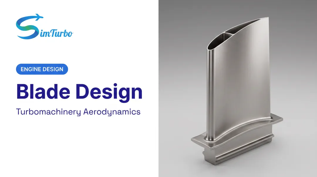
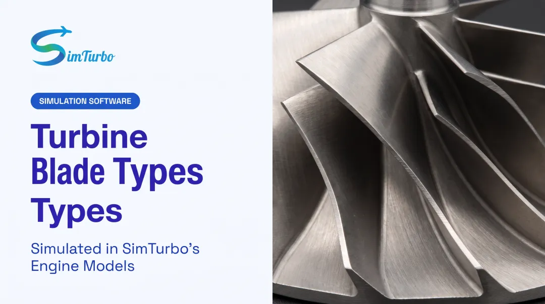
Gas turbine blades are airfoils mounted radially on a rotor disk. As combustion gas expands through them, they extract energy and convert it into shaft power that drives compressors, generators, or propellers. Each blade has three core structural elements:
- Airfoil: the aerodynamic surface that actually interacts with the gas stream
- Root: the attachment point that transfers centrifugal and aerodynamic loads into the disk
- Shroud: a tip structure on some blades that controls vibration and manages gas-path leakage
The Thermal and Mechanical Gap
Here's the core engineering problem: advanced gas turbines run rotor-inlet temperatures near 1,700°C (3,092°F). Typical blade alloys start yielding around 1,200°C (2,192°F), according to ASME research on advanced gas turbine thermal limits. That gap gets closed with cooling systems, thermal barrier coatings, and creep-resistant single-crystal alloys—not by finding a metal that simply survives on its own.
Add centrifugal loading from high rotational speeds (a NASA J85 model runs its shaft at 16,540 rpm), and you have blades that must simultaneously resist heat, creep, fatigue, and mechanical stress—often all at once, for thousands of flight hours.
Manufacturing Precision Is Non-Negotiable
Blade profile tolerances are drawing-specific rather than universal, but published research gives a sense of scale: one additive-manufacturing blade study cited profile tolerances as tight as ±100 micrometers. At that scale, a speck of dust matters.
Those same thermal, mechanical, and tolerance demands show up across every major gas turbine market.
Where Gas Turbine Blades Are Used
- Aviation propulsion (commercial and military jet engines)
- Power generation turbines (utility-scale and distributed generation)
- Marine propulsion systems
- Industrial turbochargers
Materials Used in Gas Turbine Blades
What are gas turbine blades made of? The answer depends entirely on which stage of the engine you're looking at.
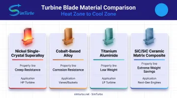
Nickel-based superalloys dominate the hottest rotating sections. Single-crystal alloys like PWA 1480 and CMSX-4 eliminate grain boundaries, which is exactly where high-temperature creep damage accumulates. These alloys maintain strength up to roughly 1,100°C (2,012°F), according to research published in AIAA's Journal of Propulsion and Power.
Cobalt-based alloys show up in some turbine buckets and guide vanes, offering strong oxidation and hot-corrosion resistance, though they trade off some high-temperature strength compared to nickel single crystals.
Titanium aluminide (TiAl) has moved into low-pressure turbine blades on modern commercial engines. GE Aerospace called welding this alloy "unthinkable ten years ago," yet it's now in production.
Ceramic matrix composites (CMCs) are the newest entrant. GE's rotating SiC/SiC CMC blade weighed about one-third of an equivalent nickel blade and didn't need second-stage air cooling at all.
Material Comparison
| Material Type | Key Property | Typical Application Area |
|---|---|---|
| Nickel single-crystal superalloy | Creep resistance, thermal stability | HP turbine (hottest rotating stages) |
| Cobalt-based alloy | Hot-corrosion/oxidation resistance | Vanes, buckets |
| Titanium aluminide | Low weight, moderate temperature capability | LP turbine |
| SiC/SiC ceramic matrix composite | Extreme weight savings, minimal cooling need | LP turbine, next-gen combat engines |
Thermal Barrier Coatings Extend the Envelope
Thermal barrier coatings (TBCs), typically yttria-stabilized zirconia over a bond coat, let the underlying metal run cooler than the surrounding gas. NASA testing showed a 190K (342°F) reduction in vane metal temperature at a specific coating thickness and coolant ratio. That's not a universal number, but it illustrates why TBCs are standard on hot-section hardware.
Engineers weigh three competing factors when selecting blade material: weight, heat resistance, and cost. A CMC blade might solve a weight problem but introduces manufacturing cost and qualification risk that a nickel alloy doesn't.
Types of Turbine Blades and HP/LP Turbine Sections
Engineers often ask what the three main types of turbine blades are. In practice, turbine staging sits on a spectrum defined by degree of reaction.
- Impulse blades (degree of reaction = 0): the entire pressure drop happens in the stationary nozzle upstream. The rotor just redirects the jet and extracts momentum.
- Reaction blades (degree of reaction near 1): most of the expansion happens inside the rotor passages themselves, not only in the nozzle.
- Intermediate-reaction (sometimes called hybrid) blades: the pressure drop is shared between stator and rotor in a set ratio. Most real turbine stages sit in this middle ground.
HP and LP Turbines Explained
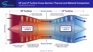
High-pressure (HP) turbines sit immediately downstream of the combustor. They face the hottest, highest-pressure gas in the entire engine. NASA data on a representative cycle shows HP turbine inlet conditions around 3,150°R (1,159°C) dropping through the stage.
Low-pressure (LP) turbines sit further downstream, extracting remaining energy at lower temperature and pressure. In that same NASA dataset, LP turbine inlet temperature drops to roughly 2,236°R (958°C).
This temperature split drives real material decisions:
- HP blades: need advanced cooling (internal channels, film cooling) plus nickel single-crystal alloys and thermal barrier coatings (TBCs)
- LP blades: can often use lighter titanium aluminide or ceramic matrix composites (CMCs) because they see less thermal stress
Blade type and HP/LP placement set the cooling load, alloy choice, and stage count. Get those wrong and you leave shaft power on the table, whether the turbine drives a compressor, generator, or propeller.
Design, Cooling, and Manufacturing Challenges
Blade aerodynamics hinge on airfoil camber, twist, and profile shape. Designers shape the surface to extract maximum energy while limiting drag and flow separation along the span.
Those same contours must leave room for cooling passages and survive steep thermal gradients. Aerodynamic gains always trade against structural strength and heat load, which is why cooling design sits at the center of hot-section work.
Cooling Techniques That Extend Blade Life
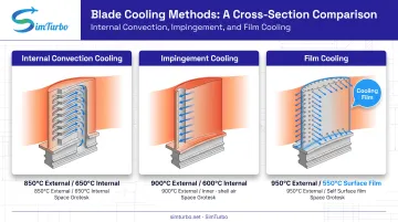
Three cooling methods work together in most hot-section blades:
- Internal convection cooling: Compressor bleed air runs through internal passages. Ribs and turns raise heat transfer, though they add some pressure loss.
- Impingement cooling: Cooling air jets strike the blade's inner shell directly. One NASA test held blade temperature to 1,255 K against a 1,644 K gas stream with this method.
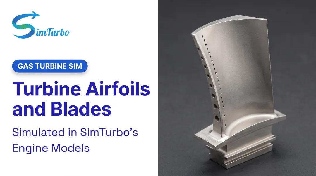
- Film cooling: Coolant exits through surface holes to form a protective layer. NASA testing found shaped holes nearly doubled cooling effectiveness compared with simple round holes.
Manufacturing Processes
Blade production relies on three primary methods:
- Investment casting with ceramic cores, using directional solidification (temperature gradients of 10–100°C/cm) to grow single-crystal structures
- Precision forging for blades that do not need internal cooling passages
- CNC machining for final root and platform features
Quality control closes the loop. Non-destructive testing (NDT) and coordinate measuring machine (CMM) inspection catch porosity, misoriented grains, and hot tears before a blade reaches a test cell. At operating speed, a hidden flaw can destroy the engine.
How Simulation Software Supports Better Blade and Engine Design
Physical blade prototyping is expensive and slow. Before committing to casting molds and forging dies, engineers increasingly model how compressor, combustor, turbine, and nozzle sections interact under both steady-state and transient conditions.
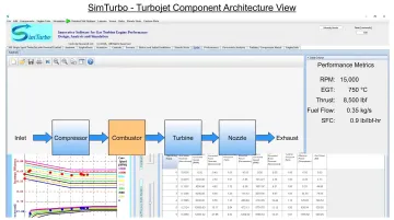
SimTurbo is built for that modeling step. The Windows-based, component-based platform lets engineers architect and re-parameterize engine models—including compressor and turbine sections that set blade operating conditions—rather than treating the whole engine as a black box.
Users can:
- Build single-spool or dual-spool turbojet models from individual components
- Model HP/LP spool interaction directly, matching the same HP/LP distinction that governs real blade design decisions
- Simulate advanced configurations like recuperated, regenerative, and afterburning cycles to see how cycle changes affect turbine operating conditions
- Export RPM, EGT, thrust, and fuel-consumption data to Excel, MATLAB, Simulink, or Python for further analysis
SimTurbo's single-spool J85-GE-21 model has been validated against NASA Lewis Research Center test data within ±2% for thrust, flow rate, temperature, and thrust-specific fuel consumption. That correlation shows software-based modeling can meaningfully complement physical blade testing and control-law validation without replacing it.
University programs and capstone teams use SimTurbo when they lack access to physical turbine hardware. A student team can study throttle response, compressor-turbine matching, and blade-stage thermal behavior on a laptop instead of a test cell.
Frequently Asked Questions
What are gas turbine blades and what are they used for?
They're airfoils mounted on a rotor disc that convert combustion gas energy into rotational shaft power, used across aircraft engines, power generation turbines, and marine propulsion systems.
Why are gas turbine blades so hard to make?
They must survive gas temperatures hotter than their own melting point, extreme centrifugal loads, and micrometer-level manufacturing tolerances, all while using superalloys that are notoriously difficult to machine and cast.
What are gas turbine blades made of?
Primarily nickel-based superalloys, with cobalt alloys, titanium aluminide, and ceramic matrix composites used in specific stages. Thermal barrier coatings are added to push operating temperatures beyond the base metal's limit.
What are the three main types of turbine blades?
- Impulse blades put the entire pressure drop in the stator
- Reaction blades share the drop between stator and rotor
- Intermediate-reaction designs fall between these two extremes
What are HP and LP turbines in a gas turbine?
The high-pressure (HP) turbine sits right after the combustor and handles the hottest, highest-pressure gas. The low-pressure (LP) turbine sits downstream, extracting remaining energy at lower temperature and pressure.