NASA's own historical figures put commercial engine development at roughly $1 billion and up to 3 years of work, with military engines stretching to a decade. Simulation-driven workflows cut engine-system simulation time by an estimated 55% throughout the product lifecycle, according to NASA reporting.
This article covers what turbine engine simulation actually models, the methods engineers use at different fidelity levels, how to pick a platform, and where these tools show up in real industry and classroom work.
Key Takeaways
- Simulation lets engineers validate performance and control behavior digitally, long before physical builds exist
- Component-based and CFD-based methods serve different needs: fast iteration versus deep physical accuracy
- Platform choice hinges on your project's speed, fidelity, and budget requirements
- Real-time tools like SimTurbo bridge design iteration and control validation without CFD-level computing costs
What Is Turbine Engine Simulation?
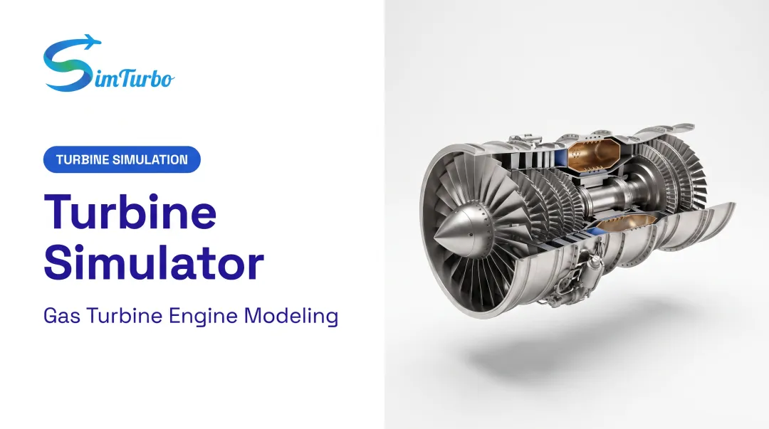
Turbine engine simulation is the digital modeling of a gas turbine's aero-thermodynamic and mechanical behavior. Instead of machining a compressor blade to learn how it performs, engineers build a computational model that predicts the same behavior on a screen.
Why Engineers Rely on Simulation
Physical testing is expensive and slow. Simulation shortens that loop dramatically. NASA/AIAA's Vision 2030 report notes that improved combustion CFD has already cut the number of combustor rig tests required over the past two decades, with projected savings of hundreds of millions of dollars across engine manufacturers.
Regulatory pressure adds another push toward simulation-first design:
- NOx and particulate standards (EASA, ICAO) that constrain the design space
- CO2 and noise limits that force iterative refinement
- Trial-and-error hardware loops that are too slow to hit those targets
Simulation lets engineers explore emissions and efficiency tradeoffs digitally before committing to hardware.
Core Elements Modeled in a Turbine Engine
A complete gas turbine model typically includes:
- Inlets — condition airflow before compression
- Compressors — raise pressure and capture surge behavior
- Combustors — mix fuel and air and release heat
- Turbines — extract energy from the hot gas path
- Nozzles — shape exhaust flow and generate thrust
- Shafts — transfer mechanical power between spools
- Recuperators — recover heat for efficiency gains
- Afterburners — add supplemental thrust when needed

Tools such as SimTurbo represent these parts in a component-based architecture rather than a single black-box engine model.
Steady-state modeling captures behavior at a fixed operating point. Transient modeling captures startup, throttle changes, and events such as compressor surge.
Real engines rarely sit still, so both matter. A steady-state-only model will miss control-response problems that appear during acceleration or shutdown.
Methods and Levels of Turbine Engine Simulation
Not all simulation approaches are equal, and picking the wrong one wastes either time or accuracy.
Component-by-Component vs. Fully Coupled
Component-by-component analysis models each part in isolation, guessing boundary conditions at each interface. It's fast, but errors compound as guesses at the compressor-combustor boundary ripple downstream.
One-way coupling improves this slightly, passing data in a single direction between components.
Fully coupled (two-way) simulation solves all components simultaneously, letting pressure and flow effects propagate in both directions. The ASME fully coupled method varies engine speed until compressor and turbine power converge, without needing prescribed internal boundary conditions.

Three CFD Fidelity Levels
| Fidelity Level | Best For | Computational Cost |
|---|---|---|
| Steady-state RANS | Design iteration backbone | Baseline cost |
| Unsteady time-domain RANS (URANS) | Blade-row unsteadiness | Higher than steady RANS |
| Unsteady frequency-domain RANS | Periodic flow phenomena | 1-2 orders of magnitude lower than URANS |
A 2022 peer-reviewed harmonic balance study found frequency-domain methods cut CPU time by one to two orders of magnitude compared to time-domain URANS, though at the cost of higher memory demand.
A Real-World Fully Coupled Case
A 2018 ASME Turbo Expo study built a fully coupled CFD methodology for a micro gas turbine engine, modeling the compressor, combustor, and both turbine stages within a single computational domain.
A separate 2022 study comparing coupled versus uncoupled CFD schemes on a full engine found both approaches stayed within a 5% error margin against experimental results. That threshold applies to that specific test, not gas turbines generally.
Real-Time Platforms vs. High-Fidelity CFD
Full CFD resolves spatial flow detail down to the mesh cell. Real-time, PC-based platforms trade that spatial resolution for speed, using thermodynamic relations, gas-property tables, and component maps instead of solving Navier-Stokes equations across a 3D mesh.
That tradeoff makes them a poor fit for blade-geometry optimization, but strong for system-level architecture and control-logic iteration in minutes rather than days—the use case tools like SimTurbo are built for.
Choosing the Right Simulation Platform for Your Project
The tradeoff comes down to depth versus speed.
- High-fidelity CFD tools: best for research, validation, and detailed aerodynamic investigation. Expect mesh counts in the millions and runtimes measured in hours or days on multi-processor clusters.
- Real-time, component-based platforms: best for rapid design iteration, control-law development, and system-level performance analysis on a standard PC.
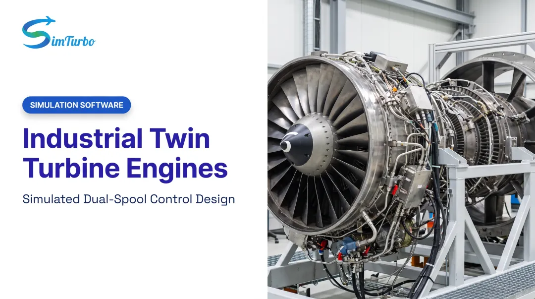
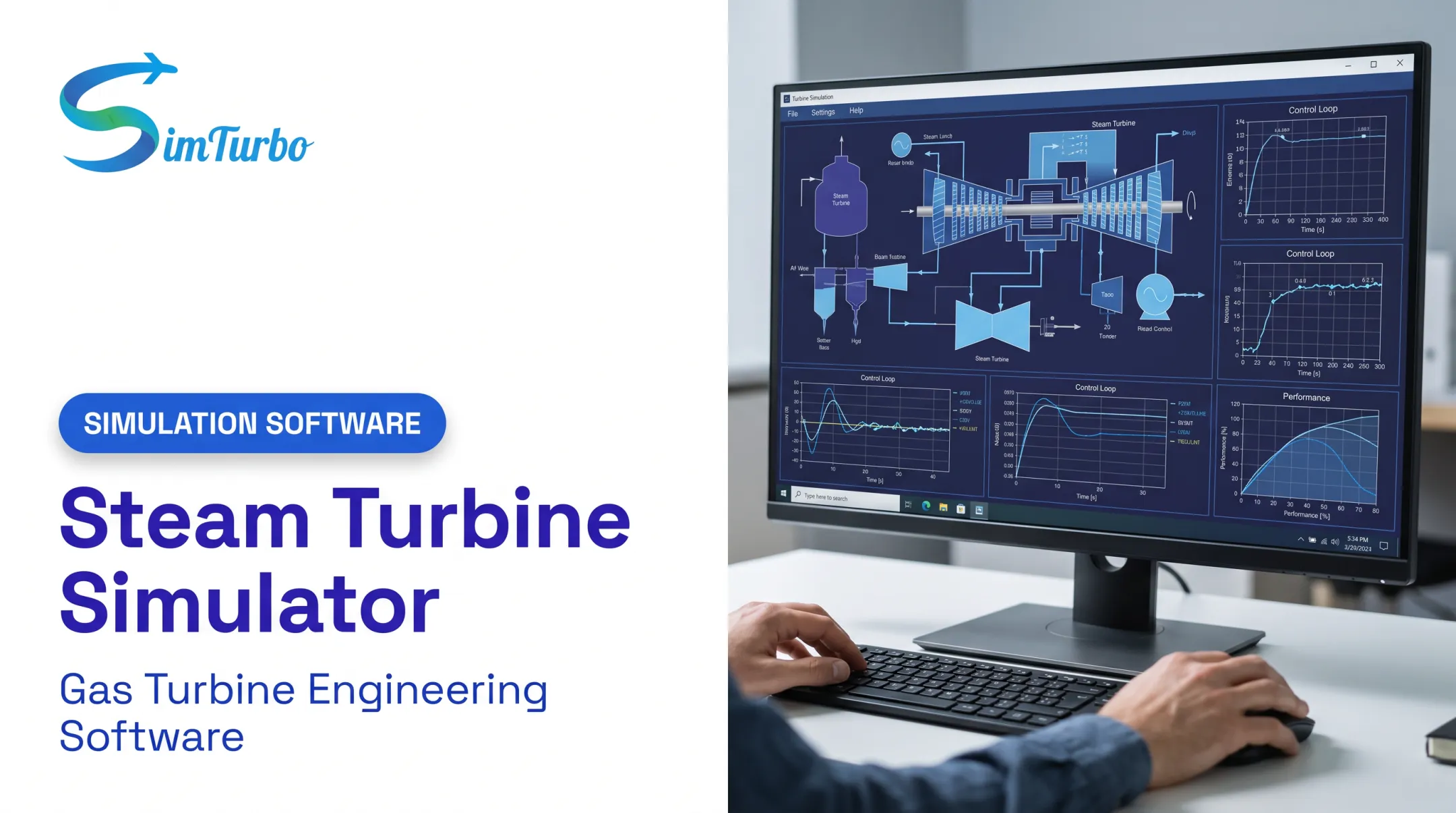
SimTurbo, built by Controls Research LLC, sits in the second category. It's a Windows-based platform with a drag-and-drop component architecture. Engineers assemble inlets, compressors, combustors, turbines, nozzles, shafts, recuperators, and afterburners into single- or dual-spool turbojet configurations.
Key capabilities include:
- Real-time transient and steady-state simulation on a standard PC (8 GB RAM, modern multi-core CPU)
- Built-in PID controllers and limiters for control-system development
- Component maps, real-gas effects, and pressure-loss modeling
- Validation against NASA Lewis Research Center J85-GE-21 test data, reporting accuracy within ±2% for thrust, flow rate, temperature, and TSFC

For post-processing, SimTurbo exports transient time-series data (RPM, EGT, thrust, SFC) in CSV and Excel formats, with support for MATLAB/Simulink and Python workflows. Engineers can then validate externally built control laws against SimTurbo's own PID and FADEC logic exported as a plant response.
Applications Across Industries and Education
Turbine engine simulation shows up wherever gas turbines get designed, tested, or taught.
Industry use cases:
- Aerospace design — architecture tradeoffs for single and dual-spool turbojets before committing to hardware
- Marine propulsion — modeling aero-derivative engines under variable load conditions
- Power generation — control validation for gas turbine power systems
Education and research:
Universities use simulation platforms for hands-on learning. Students can visualize transient throttle response and startup dynamics that a textbook diagram can't convey.
Component-based tools also support:
- Capstone teams building small-scale turbojet models
- Hybrid-electric propulsion research that ties electric motors and generators in through shaft logic
Control validation cuts across these settings. Testing a control law in simulation before hardware-in-the-loop work catches design flaws early, when they're cheap to fix rather than expensive to discover on a test stand.
Common Challenges in Turbine Engine Simulation
Simulation isn't friction-free. A few recurring pain points:
- Geometric complexity: cooling holes, combustor liner features, and multi-component interactions add modeling overhead that's easy to underestimate
- Computational demand: a documented micro-engine CFD case used a mesh of 19.2 million points across 144 processors, running roughly 24 hours to reach convergence
- Accuracy vs. turnaround: high-fidelity CFD builds confidence but costs days; real-time platforms deliver speed but skip spatial flow detail

NASA's Vision 2030 report notes that earlier full-engine simulations often relied on simplified component configurations. Resolving unsteady secondary flows and component interactions was simply too computationally expensive.
The report's own target, a full-engine model completed within one week, shows how far the industry still has to go on turnaround time, even with modern computing power.
For most design-iteration work, teams pair a fast, component-based tool for early-stage architecture decisions with high-fidelity CFD reserved for final validation.
Frequently Asked Questions
What is the purpose of turbine engine simulation?
Turbine engine simulation predicts engine performance, transient behavior, and control response digitally—before any physical hardware exists. That early visibility catches design flaws and cuts costly late-stage surprises.
How accurate are gas turbine simulation models?
Accuracy depends on the tool and validation dataset. SimTurbo's J85-GE-21 validation against NASA Lewis Research Center data reported agreement within ±2% for thrust, flow rate, temperature, and TSFC.
What software is used for gas turbine simulation?
High-fidelity CFD tools handle deep aerodynamic research, while real-time platforms like SimTurbo target rapid design iteration and control-law development. The right choice depends on whether you need spatial flow detail or system-level speed.
Can simulation replace physical engine testing?
No. Simulation reduces the number of physical tests needed and catches problems earlier, but hardware validation remains necessary before certification and deployment.
How is turbine engine simulation used in education?
Universities use turbine engine simulation for classroom instruction, lab exercises, and capstone projects so students can visualize transient effects like startup dynamics and throttle response in real time.
What components of a gas turbine can be simulated?
Inlets, compressors, combustors, turbines, nozzles, shafts, recuperators, and afterburners can all be modeled individually or assembled into a complete engine architecture.