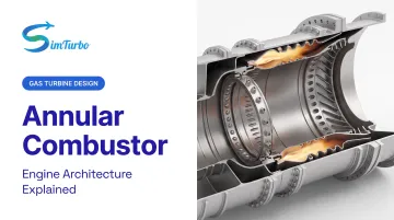
This article explores the architecture, components, and performance advantages of annular combustors, compares them with earlier can and can-annular designs, and examines modern developments including double annular combustors and emissions-reduction technologies.
Key Takeaways
- Annular combustors are continuous ring chambers that replaced segmented designs in most jet engines
- They beat can and can-annular types on compact packaging, fewer duplicated surfaces, and continuous mixing
- Core parts: liner, dome/swirler assembly, fuel injection system, and diffuser
- CFM, Pratt & Whitney, and most modern turbofan makers rely on annular layouts
- Double annular and other staged variants cut NOx by separating combustion zones
What Is an Annular Combustor?
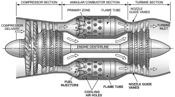
An annular combustor is a continuous ring-shaped combustion chamber positioned between the compressor and turbine sections of a gas turbine engine. According to FAA technical documentation, the combustor receives high-pressure air from the compressor, mixes it with fuel, ignites and sustains combustion, then delivers controlled hot gases to the turbine.
Geometry and Architecture
The defining characteristic of the annular design is its continuous geometry: a single uninterrupted liner and outer casing form a ring (or annulus) around the engine's central axis. Multiple fuel injectors, distributed circumferentially around the ring, supply atomized fuel to the combustion zone. That layout differs from the segmented can and can-annular designs used in earlier engines.
NASA describes the annular arrangement as a liner inside an outer casing, noting that many modern burners use this configuration. The continuous flame volume eliminates the structural and aerodynamic penalties of separate combustion cans.
Historical Development
Annular combustors became dominant during the 1960s and 1970s as materials science and manufacturing techniques advanced to handle the more complex geometry. NASA documented an advanced full-scale annular combustor in 1969, followed by a low-cost small-turbojet annular test in 1973.
These early NASA experiments showed the design could work at different scales and performance targets, which supported broader commercial use. Builders moved from can-type combustors to annular designs to cut weight, shrink engine length, and improve fuel efficiency.
Earlier Segmented Designs
Those gains are clearer when set against the layouts annular combustors replaced. Before annular designs took over, engines used:
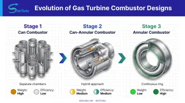
- Can combustors: 8–12 self-contained cylindrical chambers, each with its own fuel injector and liner
- Can-annular combustors: Discrete combustion zones in separate liners sharing a common annular casing, with connecting tubes for ignition propagation
The continuous annular geometry eliminated the weight, surface area, and pressure-loss penalties of duplicated structures, establishing a new performance baseline for high-thrust turbofan and turbojet engines.
Key Components of Annular Combustor Design
Annular combustors integrate several subsystems to achieve stable, efficient, high-temperature combustion within stringent weight and space constraints.
Liner
The liner contains the combustion process and must withstand extreme temperatures while metering cooling and dilution air. NASA's 1987 liner research evaluated advanced constructions including:
- Hastelloy X superalloy combined with Hoskins 875 wire and yttria-stabilized zirconia (compliant metal/ceramic configuration)
- Lamilloy transpiration panels
- Counter-flow film-cooled finned panels
These experimental liners were designed for a maximum 1,200 K liner temperature, with the combustor outlet-temperature target reaching 1,922 K. Transpiration and counter-flow film-cooled liners reduced coolant flow by 40–50% compared to conventional splash-film designs, while the compliant metal/ceramic construction achieved an 80% reduction.
Dome and Swirler Assembly
The dome directs primary air into the combustion zone, while swirlers create turbulence to rapidly mix fuel and air. NASA's CFD evaluation of a lean-direct-injection combustor predicted central recirculation zones behind pilot elements and additional recirculation generated by main-element swirlers. These recirculating flows stabilize the flame and promote complete fuel-air mixing without excessive pressure loss.
Fuel Injection System
Multiple fuel injectors, positioned circumferentially around the annulus, atomize fuel for complete combustion. Modern air-blast or pre-mixing/pre-vaporizing injector types replace older simplex pressure-atomizing designs.
For example, NASA's QCSEE double-annular combustor used 20 swirlers in each annulus with simplex pressure-atomizing nozzles in both pilot and main stages. The exact injector count and configuration vary by engine size, performance targets, and emissions requirements.
Case and Diffuser
The outer casing serves as a pressure vessel, containing combustion pressure loads. The diffuser decelerates high-velocity compressor discharge air to optimal combustion speeds. Excessive velocity inhibits flame stability; insufficient deceleration increases pressure loss.
Air Flow Management
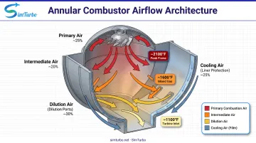
Combustor air is divided into four functional paths:
- Primary combustion air: Enters through the dome and swirlers to mix with fuel
- Intermediate air: Completes combustion downstream of the primary zone
- Dilution air: Reduces gas temperature to turbine-acceptable levels
- Cooling air: Protects the liner through film or transpiration cooling
NASA research shows that increasing cooling air reduces primary swirler air and raises primary-zone temperature. That tradeoff is a coupled design balance engineers must optimize for each application.
Annular vs. Can and Can-Annular Combustors
The three basic combustor topologies reflect different eras of gas turbine development and offer distinct trade-offs.
Can Combustors
Can combustors consist of 8–12 separate cylindrical chambers distributed around the engine, each with its own fuel injector and liner. Advantages include easy maintenance, modular replacement, and individual chamber testing.
Disadvantages include:
- Higher total weight due to duplicated structure
- Greater total surface area requiring cooling
- Less efficient use of circumferential space
Can-Annular Combustors
Can-annular designs represent a hybrid approach: discrete combustion zones in separate liners share a common annular casing. Chambers communicate via connecting tubes to propagate ignition and equalize pressure. This middle-ground architecture offers:
- Shared outer casing (weight savings vs. full can design)
- Individual flame-tube serviceability
- Intermediate performance between can and annular types
Annular Performance Advantages
Annular combustors deliver:
- Compact axial packaging with the shortest length among the three types
- Reduced liner and casing surface area to cool
- Circumferentially continuous mixing for more uniform combustion and exit temperature
- Lower structural weight from a single continuous structure
NASA test data show that pressure loss and combustion efficiency depend heavily on operating conditions, diffuser design, and cooling-flow allocation.
A 1969 advanced annular combustor measured near 6% total-pressure loss at takeoff and near 8% at cruise. A 1973 low-cost annular design recorded 8.8% at altitude cruise and 9.8% at sea-level cruise, with roughly 94% combustion efficiency at altitude cruise and 96% at sea-level design point. Exact values stay application-specific, but annular designs can deliver high efficiency with manageable pressure loss.
Comparison Summary
| Combustor Type | Geometric Structure | Qualitative Pressure Loss | Weight | Maintenance |
|---|---|---|---|---|
| Can | 8–12 separate cylindrical chambers | Higher | Highest | Modular, easy |
| Can-Annular | Discrete liners in shared casing | Intermediate | Intermediate | Moderate |
| Annular | Single continuous ring | Lowest | Lowest | Requires full-access tooling |
While annular combustors require full-size test rigs and more complex service procedures, their performance benefits make them the preferred choice for modern high-performance engines.
Advantages and Applications
Performance Benefits
Annular combustors offer:
- More uniform combustion — continuous geometry cuts hot spots and inter-can variations
- Lower weight from fewer duplicated surfaces and a shorter axial package
- Smaller cooling-air demand because less liner surface needs protection
- Better fuel efficiency through complete combustion and cleaner air distribution
Modern Engine Applications
Nearly all contemporary commercial turbofan engines use annular combustors. Notable examples include:
- CFM International CFM56: Single- and double-annular variants power the Airbus A320ceo and Boeing Next-Generation 737, among the most-produced turbofan families in service.
- Pratt & Whitney Canada PW123: Annular reverse-flow combustor used on regional turboprops such as the ATR 42/72 and Dash 8/Q Series.
- Pratt & Whitney Canada PT6 and PW200: Reverse-flow annular chambers; a 2007 technical paper cites combustion efficiency above 99.5% over most of the operating range.
Industry Adoption
The same layout now leads most advanced military engines as well. Smaller turboshafts with centrifugal compressors still use can combustors in places, but medium- and high-thrust programs have largely standardized on annular designs.
Reverse-flow annular layouts (air turns aft before the flame zone, then forward again) keep the engine short for turboprops and turboshafts, so the annular approach fits more than high-bypass turbofans alone.
Modern Developments in Annular Combustor Technology
Double Annular Combustors (DAC)
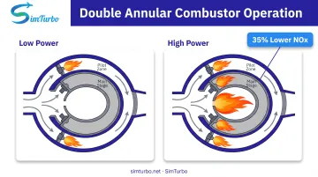
Double annular combustors represent an advanced variation with two concentric combustion zones: an outer pilot stage and an inner main stage. CFM's DAC technology adds a second dome and optimizes performance across power settings.
Staging strategy:
- Low power: Only the outer pilot zone operates, maintaining stable combustion
- High power: Both zones operate; most fuel and air pass through the inner main stage
This approach reduces flame temperature and residence time at high power, delivering 35% lower nitrogen oxide (NOx) emissions compared to CFM's single-annular baseline. CFM attributed the reduction to greater burning-zone velocity, shorter residence time, and lower flame temperature. The first CFM56-5B with DAC entered service in early 1995 with Swissair and Austrian Airlines.
Emissions Reduction Technologies
Modern annular combustors incorporate several emissions-control strategies:
- Lean-burn technology: Operates with excess air to reduce peak flame temperature and NOx formation
- Improved fuel atomization: Smaller droplets promote complete combustion and minimize unburned hydrocarbons
- Optimized air-fuel mixing: Front-end premixing and swirler designs improve combustion uniformity
GE's Twin Annular Pre-mixing Swirler (TAPS) lineage, used in commercial GEnx and LEAP engines, employs front-end fuel-air premixing to reduce NOx while maintaining combustion stability across the operating envelope.
Advanced Design and Simulation Tools
Engineers use computational fluid dynamics (CFD) and specialized simulation platforms to model combustor performance, validate designs, and optimize parameters before physical testing.
NASA's 2017 CFD evaluation of a lean-direct-injection combustor used the National Combustor Code to predict airflow, recirculation, flame structure, temperature fields, and cooling-flow effective area. CFD/experiment differences in effective area were 6–8%, within the program's pre-established 10% acceptance margin.
Simulation platforms like SimTurbo enable real-time modeling of annular combustor behavior within complete gas turbine engine systems. Engineers can examine combustion heat addition on Temperature-Entropy diagrams and watch transient temperature shifts during throttle bursts.
The same environment supports steady-state and transient analysis, so users can check combustor effects on turbine inlet temperature, surge margin, and cycle performance before hardware runs. SimTurbo’s J85-GE-21 validation matched NASA test data within ±2% for thrust, flow rate, temperature, and thrust-specific fuel consumption.
Used early, these tools cut physical test loops and give university labs a practical way to teach combustor behavior inside a full engine model.
Frequently Asked Questions
What are the key differences between annular and can-annular combustors?
Annular combustors use a single continuous ring liner, while can-annular designs retain discrete combustion zones in separate liners that share a common casing. Annular configurations provide more uniform temperature distribution, lighter weight, and compact axial packaging compared to can-annular types.
What does a combustor do?
A combustor adds energy to the engine by mixing compressed air with fuel, igniting and sustaining combustion, then delivering hot high-pressure gases to the turbine. It must maintain stable combustion across a wide range of operating conditions while controlling exit temperature and minimizing emissions.
What are the four types of combustors?
The four main types are can, can-annular, annular, and double annular. Can, can-annular, and annular are the basic topologies; double annular is a staged annular variant with pilot and main zones for better emissions control across power settings.
What is an annular reverse flow combustion chamber?
Reverse-flow annular combustors direct airflow backward (opposite to main engine flow) before combustion, then forward again. This compact design appears in turboprop and turboshaft engines such as the Pratt & Whitney Canada PW123, PT6, and PW200.
What are the main advantages of annular combustors over earlier designs?
Annular combustors provide compact axial length, reduced total surface area requiring cooling, more uniform exit temperature, and lighter weight. Their continuous geometry eliminates the structural duplication of can combustors and supports circumferentially continuous mixing.
Which modern aircraft engines use annular combustors?
The CFM56 family (Boeing 737, Airbus A320), Pratt & Whitney Canada PW123 (ATR 42/72, Dash 8), and most contemporary turbofan engines use annular configurations. The trend toward annular designs reflects their performance advantages in commercial aviation and advanced military applications.