Multi-loop PID control addresses this by coordinating multiple interconnected controllers, each assigned to a specific variable but working in harmony with the others. This article explains when to choose multi-loop architectures, how to pair loops correctly, and how to tune them sequentially to avoid instability. We'll walk through cascade, feedforward-feedback, and override structures, then outline a step-by-step design methodology supported by simulation, pairing analysis, and bandwidth separation principles.
Key Takeaways
- Multi-loop PID coordinates multiple controllers to manage interacting process variables simultaneously
- Cascade control achieves fast disturbance rejection by nesting a quick inner loop inside a slower outer loop
- Loop pairing and sequential tuning (inner-first, then outer) deliver stable, robust performance
- MIMO processes need multi-loop architectures plus careful interaction analysis and validation
- Real-time simulation validates designs and tunes controllers before hardware deployment
Understanding Multi-Loop PID Control Systems
What Multi-Loop PID Control Is
Multi-loop PID control uses two or more PID controllers working together to regulate a process. Each controller owns a controlled variable (CV) and manipulated variable (MV) pair.
In single-loop control, one controller drives one actuator to hold one CV. In multi-loop systems, several controllers and actuators run at once, and process dynamics couple them: changing one MV affects more than one CV.
Single-loop vs. multi-loop:
- Single-loop: One controller → one actuator → one CV
- Multi-loop: Multiple controllers → multiple actuators → multiple CVs, with cross-coupling
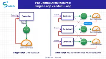
That structure handles processes with multiple disturbances, separated time scales, and interacting dynamics. You can reject disturbances closer to their source, enforce safety limits, and hold tighter setpoint tracking across several objectives at once.
Why Multi-Loop Control Is Necessary
Many industrial processes have several control objectives a single controller cannot meet. A gas turbine, for example, must regulate rotor speed, turbine temperature, and surge margin at the same time. The same pattern shows up in reactors, distillation columns, and multi-axis machines.
Loop interaction is the core challenge. In multiple-input multiple-output (MIMO) plants, one controller’s move changes other loops’ CVs. Without coordination, loops fight each other and produce oscillation, sluggish response, or instability.
Common multi-loop applications:
- Gas turbine engines (fuel flow, rotor speed, turbine temperature)
- Distillation columns (temperature, pressure, level)
- Chemical reactors (temperature, pressure, composition)
- Robotic manipulators (position, velocity, torque per joint)
Core Components and Signal Flow
A typical multi-loop system includes:
- Multiple PID controllers, each with its own tuning parameters
- A MIMO process whose dynamics couple the loops
- Sensors for every controlled variable
- Cross-paths where one controller’s output changes another loop’s response
Each controller compares a setpoint to a measurement, computes a control action, and drives an actuator. Because the plant is MIMO, that action travels through shared dynamics and changes the process the other loops see. You have to account for that cross-coupling in pairing, tuning, and validation.
Single-Loop vs. Multi-Loop: When to Use Each
Match the controller structure to how many variables you must hold, where disturbances enter, and how strongly the loops interact.
| Decision Condition | Preferred Structure | Reason |
|---|---|---|
| Single CV, single MV, one dominant time constant, minimal disturbances | Single-loop PID | Simplicity; no coordination needed |
| Multiple CVs and MVs; manageable cross-coupling | Multi-loop decentralized PID | Accounts for interaction while preserving simple, maintainable controllers |
| Measurable fast secondary variable between actuator and primary CV | Cascade control | Inner loop rejects local disturbances before they reach the primary variable |
| Measurable disturbance enters before CV responds | Feedforward-feedback | Proactive correction on the disturbance; feedback handles model error |
| Shared actuator must respect a safety or operating constraint | Override/selector control | Transfers authority to the limiting loop; protects against unsafe conditions |
Trade-offs:
- Single-loop: Simple to design, tune, and maintain. Limited when multiple objectives or disturbances exist.
- Multi-loop: Stronger disturbance rejection, tighter control, and constraint handling. More complexity, harder tuning, and instability risk if pairing is poor.
Choose multi-loop when you have multiple controlled variables, disturbances at different points, widely separated time scales, or when stronger disturbance rejection justifies the extra complexity.
Common Multi-Loop Architectures
Multi-loop designs pair two or more controllers so each handles a different dynamic or constraint. The patterns below are the ones you will see most often in process and turbomachinery control.
Cascade Control (Master-Slave)
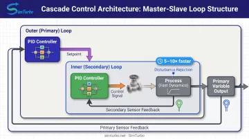
Cascade control nests a fast inner (secondary) loop inside a slower outer (primary) loop. The outer controller's output becomes the inner controller's setpoint; the inner controller drives the actuator directly.
Classic example: Gas turbine exhaust temperature (outer loop) cascaded with fuel flow (inner loop). Supply-pressure disturbances are corrected by the fast flow loop before they drive EGT off target.
Bandwidth relationship: The inner loop should be about 5× faster than the outer for effective disturbance rejection and stability. A 2016 ISA screening guideline uses this same ratio; treat it as a starting rule, not a hard requirement.
When to use cascade:
- A fast secondary variable exists between the actuator and primary variable
- Disturbances affect the secondary variable
- The inner loop can be tuned significantly faster than the outer
Feedforward-Feedback Control
This architecture combines feedforward control, which acts on measurable disturbances before they affect the process, with feedback PID, which corrects for unmeasured disturbances and model inaccuracies.
How it works:
- Feed a measurable disturbance (e.g., inlet temperature change) into a model or ratio block
- The feedforward action preemptively adjusts the manipulated variable
- The feedback PID corrects residual error from model mismatch and unmeasured disturbances
When to use:
- Major disturbances are measurable (inlet flow, feed composition, ambient temperature)
- You want proactive rather than purely reactive control
- The disturbance model and timing are reasonably accurate
Feedforward lightens the load on feedback, cutting response time and overshoot. Accurate models and timing still matter; feedback remains essential for model error and unmeasured disturbances.
Ratio and Override Control
Ratio control maintains a fixed ratio between two process variables. One controller sets the primary (or "wild") flow; the other adjusts a secondary flow to maintain the ratio.
Example: Fuel-to-air ratio in combustion. Air flow is measured; fuel flow is adjusted to maintain the desired stoichiometric ratio.
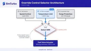
Override (selective) control uses high or low selectors to transfer control authority among multiple controllers competing for a shared actuator. The system picks the controller that keeps the process safest.
Example: In compressor control, a selector prevents surge by opening a recycle valve when the operating point approaches the surge line, overriding normal flow control.
When to use ratio control: Blending, combustion, or reactant stoichiometry: any process that needs a fixed relationship between flows.
When to use override control: Shared actuators with safety or operating constraints (surge protection, temperature limits, pressure limits).
Designing Multi-Loop PID Controllers: Step-by-Step
Step 1: Process Analysis and Loop Pairing
Document the system:
- Identify all controlled variables (CVs), manipulated variables (MVs), and key disturbances
- Build a steady-state gain matrix showing how each MV affects each CV
- Measure or model the dynamic response (time constants, delays) for each path
Perform loop pairing analysis:
- Use the Relative Gain Array (RGA) to minimize interaction
- Prefer RGA elements closest to 1.0 (indicating little steady-state interaction from other loops)
- Avoid negative or very large RGA elements, which signal poor pairing and potential instability
- For systems larger than 2×2, supplement RGA with the Niederlinski index to check stability
Poor pairing causes loops to fight each other. If one loop's action undermines another's objective, no amount of tuning will deliver stable, high-performance control.
Step 2: Define Control Objectives and Bandwidth Requirements
Specify performance for each loop:
- Setpoint tracking speed (rise time, settling time)
- Disturbance rejection capability
- Overshoot and steady-state accuracy limits
- Actuator saturation constraints
Establish bandwidth hierarchy:
- Identify which loops must be fast (inner, secondary) vs. slow (outer, primary)
- Base bandwidth separation on disturbance frequencies and process time constants
- A 5:1 to 10:1 bandwidth ratio between inner and outer loops in cascade control is a common guideline
Faster loops settle quickly and appear as modified dynamics to slower loops, which cuts interaction and simplifies outer-loop tuning.
Step 3: Select Controller Structure for Each Loop
Choose PID type (P, PI, or PID):
- Use PI for integrating processes or when eliminating steady-state error is critical
- Use PID when derivative action improves response without excessive noise sensitivity
- Use P-only rarely, typically for very fast loops or when integral action causes instability
Practical considerations:
- Anti-windup: Essential for loops that may saturate; prevents integral buildup during saturation
- Derivative filtering: Reduces noise sensitivity; commonly applied to the measurement rather than the error to avoid setpoint kick
- Gain scheduling: Adjust PID parameters across operating conditions if process gains or dynamics change significantly
Step 4: Model the Multi-Loop System
Develop mathematical models for each process element, including cross-coupling transfer functions that show how one loop's action affects another loop's controlled variable.
Accurate models let you predict loop interaction, test pairing choices, and simulate tuning strategies before hardware deployment. They also surface instability, saturation, and robustness risks early.
Tools: Use simulation platforms to represent the complete multi-loop system. SimTurbo, for example, provides real-time, physics-based gas turbine simulation with built-in PID controllers, limiters, actuators, and sensors. Engineers can design and validate multi-loop architectures (coordinated speed, temperature, and surge-margin loops) in a virtual environment before hardware testing.
Step 5: Initial Controller Tuning
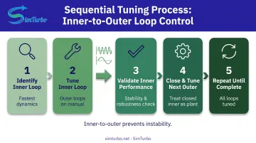
Tune sequentially, from inner to outer:
- Start with the innermost/fastest loop: Place outer loops on manual or open-loop. Tune the inner loop using standard PID methods (Ziegler-Nichols, IMC, frequency-response, model-based).
- Close the inner loop and validate: Ensure stable, robust performance before moving outward.
- Tune the next outer loop: Treat the closed inner loop as part of the effective plant dynamics. Repeat until all loops are tuned.
Faster loops settle before slower loops can respond, so interaction stays manageable during tuning. Working outer-first is riskier: the effective plant shifts unpredictably each time an inner loop closes later.
A 2022 HVAC field study across 9 air-handling units reported 2.2%–4.4% energy savings and elimination of 10–20 valve cycles per hour after implementing cascade control, demonstrating measurable benefits when multi-loop tuning is done correctly.
Tuning Strategies for Multi-Loop Systems
Sequential Loop Closure Method
Tune and close loops from innermost (fastest) to outermost (slowest), treating each previously closed loop as part of the effective plant.
Faster loops settle quickly and present modified dynamics to slower loops, so tuning in sequence minimizes the interaction you see during the process.
Validate each loop’s step response, disturbance rejection, and stability margins before closing the next outer loop. Do not proceed if the inner loop shows poor performance or weak robustness.
Detuning for Stability
Tightly tuned loops can interact and cause oscillation or instability in multi-loop systems. Detuning intentionally reduces controller aggressiveness so you get more bandwidth separation and less coupling.
One common method uses a detuning factor F: divide the controller gain by F and multiply the integral time by F. Increase F until robustness targets (phase margin, gain margin) are met.
Typical robustness targets are 30–60° phase margin, gain margin of 2–5, and maximum sensitivity of 1.4–2. Treat them as practical benchmarks, not universal rules.
Ensure the faster loop’s bandwidth stays about 5–10× the slower loop after detuning.
Decoupling Techniques
Decoupling control adds compensators that predict and cancel cross-coupling between loops. Static or dynamic decoupling can improve performance when interaction is strong.
Decoupling is worth the complexity when:
- RGA elements sit far from 1.0 (high steady-state interaction)
- Sequential tuning alone cannot meet tight performance specs
- You have accurate process models and manageable model uncertainty
The trade-off is complexity and model dependence. Bad decoupling can hurt performance or stability if the model is wrong, so test robustness to model error before you deploy compensators.
Gain Scheduling and Adaptive Tuning
Gain scheduling changes PID parameters with operating conditions (for example, low vs. high throughput) so performance holds across a wide range.
Adaptive tuning automatically adjusts controller parameters from observed process behavior or online system identification.
Use these advanced techniques when:
- Dynamics are highly nonlinear (batch reactors, variable-speed turbines)
- Time-varying parameters make fixed-gain PID insufficient
- Process gains or time constants change widely across the operating envelope
NASA gas turbine engine control documentation is a clear example: fuel-flow schedules plus limit logic for surge/stall, over-temperature, overspeed, and over-pressure. That is operating-envelope scheduling for complex turbomachinery.
Performance Validation and Iteration
Test the multi-loop system under realistic conditions:
- Setpoint changes on each loop, alone and together
- Disturbances injected at multiple points
- High/low load, startup, and shutdown
- Actuator saturation and sensor noise
Watch for interaction symptoms:
- Oscillations that appear only when multiple loops are active
- One loop’s action driving another to overcorrect or hunt
- Stability loss at specific operating points
Track IAE, settling time, overshoot, total variation of the control signals, and cross-loop excursions. Run the same checks on 2×2 and 3×3 pairings so interaction shows up before you freeze gains.
For gas turbine and other high-risk plants, validate multi-loop PID, limiters, and actuator/sensor behavior in simulation first—platforms such as SimTurbo let you stress setpoint moves, disturbances, and envelope limits before hardware commit.
Applications in Complex Systems
Gas Turbine Engines
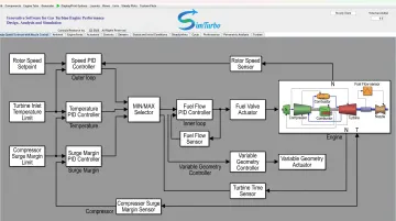
Gas turbines use multi-loop control to manage rotor speed, turbine inlet temperature, surge margin, and acceleration/deceleration limits. Typical architectures include:
- Speed control (outer loop) → fuel-flow control (inner loop)
- Temperature limiting to prevent over-temperature damage
- Surge-margin control to keep the compressor operating line safe
- Override/selector logic applying min/max selection for fuel rate, nozzle area, and variable stator-vane control
Published work on micro-gas-turbine control describes PID-based speed loops with temperature, acceleration, and maximum-fuel limiting. NASA turbine-control practice treats fuel flow as the commanded variable, with parallel limit loops for speed, temperature, surge/stall, overspeed, and pressure.
Chemical Process Industries
Distillation columns need coordinated temperature, pressure, and level loops:
- Pair reflux rate and reboiler duty to composition or inferential temperature
- Account for strong tray-to-tray coupling when choosing loop pairing and tuning
Reactors balance temperature, pressure, and composition objectives:
- Cascade temperature to steam flow or coolant flow
- Use feedforward on feed composition or inlet temperature to cut disturbance impact
Real-Time Simulation and Validation
Before hardware tests, engineers design, tune, and validate multi-loop strategies in simulation. SimTurbo is a real-time, physics-based environment for gas turbine and power systems. Its component-based architecture includes configurable PID controllers, limiters, actuators, sensors, and FADEC logic.
You can wire interconnected speed, temperature, and surge-margin loops, adjust tuning during a run, and watch transients under throttle changes, startup sequences, and sensor failures.
A J85-GE-21 turbojet model checked against NASA test data stayed within ±2% on thrust, flow rate, temperature, and thrust-specific fuel consumption. That level of agreement supports control-system validation before hardware testing.
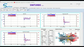
Transient data (RPM, temperature, thrust) exports to CSV or Excel for post-processing in MATLAB, Simulink, or Python, so control work can stay in familiar tools. Universities and labs also use the same environment—with educational licensing and a free 30-day trial—to teach multi-loop PID design in courses and capstone projects.
Frequently Asked Questions
What is a PID control loop?
A PID control loop is a feedback system that minimizes error between a setpoint and a measured process variable. It combines Proportional action on current error, Integral action to remove steady-state offset, and Derivative action to dampen rate of change.
What are the different types of PID controllers?
The main types are P, PI, PD, and full PID, in parallel or series form. Use PI when you need zero steady-state error; add D (full PID) when you need faster response without excessive overshoot.
What is the main advantage of cascade control over single-loop control?
Cascade control rejects disturbances faster by correcting them in a fast inner loop before they reach the primary controlled variable. That yields tighter control and less variability when disturbances hit an intermediate variable between the actuator and the primary objective.
How do you determine the correct bandwidth for inner vs. outer loops?
Keep the inner loop bandwidth about 5–10 times higher than the outer loop so the loops stay separated. An ISA guideline targets a 5:1 speed ratio for strong disturbance rejection; smaller separations can still work with conservative tuning.
What is loop interaction and why does it matter?
Loop interaction happens when one loop’s action changes another loop’s controlled variable in a MIMO system. Strong interaction can cause oscillations or instability unless you address it with RGA pairing, sequential (inner-first) tuning, detuning, or decoupling.
When should I use multi-loop control instead of advanced MIMO controllers?
Use multi-loop PID when interaction is moderate and you want simple, maintainable control that operators already understand. Choose advanced MIMO methods (MPC, H-infinity) when cross-coupling is severe or you must optimize multiple objectives and constraints in one framework.