Key Takeaways:
- Recuperators preheat compressed air using turbine exhaust, reducing fuel consumption and increasing thermal efficiency
- Microturbines see the largest gains—up to 30% electrical efficiency versus 16-20% without recuperation
- Counterflow designs with effectiveness above 90% and pressure loss below 3% represent current best-practice targets
- Recuperators add 25-30% to system cost but deliver fuel savings in high-utilization applications
- Most effective in low-compression-ratio turbines (approximately 3-5:1); benefits diminish at higher ratios
What is a Gas Turbine Recuperator?
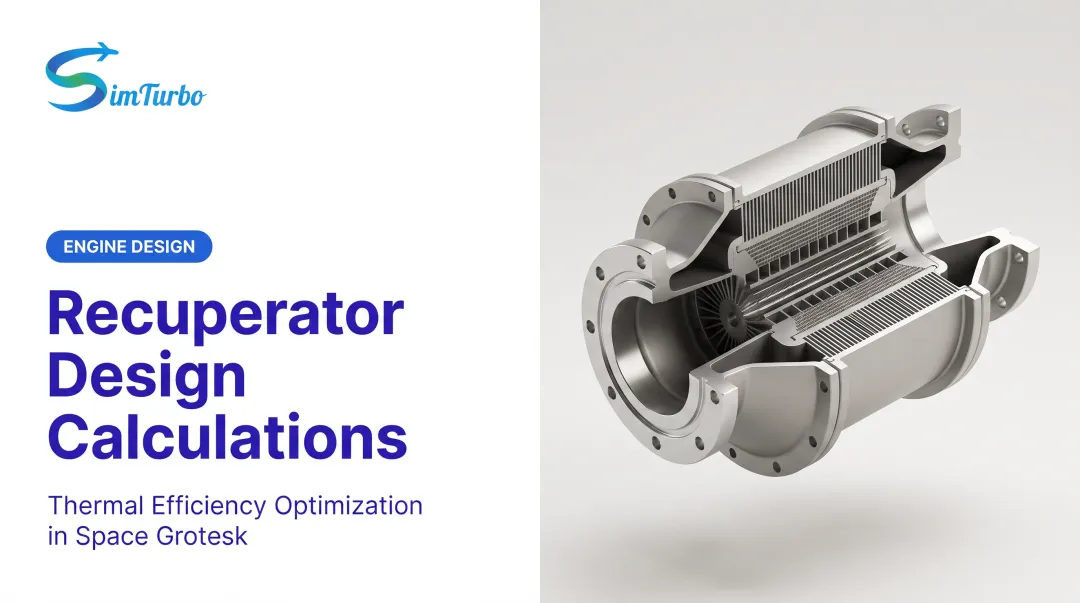
A gas turbine recuperator is a specialized counterflow heat exchanger that preheats compressed air before combustion by capturing waste heat from the turbine exhaust. Unlike general-purpose heat exchangers, recuperators are built for gas-to-gas transfer inside a power cycle.
They recover heat that would otherwise leave in the exhaust stack, so less fuel is required to reach the target combustor temperature.
How a Recuperator Works
The recuperator sits between the compressor and the combustor. It creates two isolated flow paths: compressed air absorbs heat through thin metal plates or tube walls, while hot turbine exhaust passes on the opposite side and transfers energy without mixing the streams.
That preheating cuts burner fuel demand and raises overall cycle efficiency.
Recuperators are heat exchangers, but not every heat exchanger is a recuperator. The difference is cycle role and design intent:
- Counterflow gas-to-gas layout that holds a strong temperature differential along the core
- Integration into a Brayton cycle to improve work output per unit of fuel
- High-temperature gas-phase duty, typically handling exhaust at about 400–650°C (750–1200°F) with minimal pressure penalty
Construction and Use
Most units use one of two primary builds:
- Plate-fin stacks — thin stainless or high-alloy plates with corrugated fins that form many narrow parallel channels
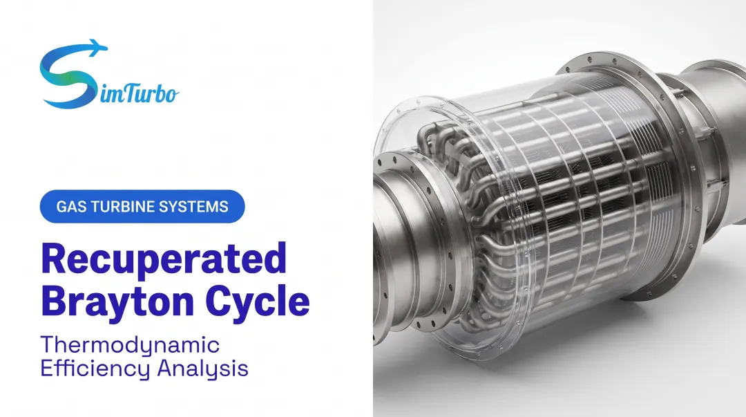
- Tubular arrays — tubes carrying compressed air surrounded by exhaust (or the reverse), chosen to suit pressure and packaging limits
Both aim for high surface area in a compact volume and trade heat-transfer effectiveness against weight and pressure drop.
Interest in recuperators rose again in the 1990s as distributed generation and microturbines grew. Early gas turbines favored compactness and simplicity over efficiency; higher fuel costs and tighter emissions rules reversed that priority. Recuperation is now standard on microturbines below 1 MW and increasingly common in industrial and marine plants where fuel dominates lifecycle cost.
How Gas Turbine Recuperators Work
Energy Transfer Process
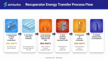
The recuperator moves heat from turbine exhaust into compressor discharge air in a clear sequence:
- Compressed air exits the compressor at elevated pressure and temperature (typically 200–400°C, depending on pressure ratio)
- Air enters the cold side, flowing through narrow channels or tubes
- Hot turbine exhaust (400–650°C) flows through adjacent hot-side channels
- Heat conducts through the separator walls (thin metal plates or tube walls), driven by the temperature difference
- Preheated air exits at 350–550°C into the combustor, so less fuel is needed to reach turbine inlet temperature
- Cooled exhaust leaves to atmosphere or downstream heat recovery after giving up much of its energy
Why Counterflow is Superior
Recuperators use counterflow arrangement: hot exhaust and cold compressed air travel in opposite directions. This configuration maintains a more uniform temperature difference along the entire heat exchanger length compared to parallel flow or crossflow designs.
In counterflow, the coldest air meets the coolest exhaust, and the hottest air meets the hottest exhaust. That layout preserves driving force along the core, so you get more heat transfer for a given surface area, or a smaller, lighter unit for the same effectiveness.
Recuperator Effectiveness
Effectiveness quantifies how much heat the recuperator actually recovers compared to the theoretical maximum. A recuperator with 90% effectiveness means the compressed air temperature rises 90% of the way from its compressor-exit temperature toward the turbine-exhaust temperature.
According to a 2017 peer-reviewed analysis of micro-gas-turbine recuperators, effectiveness above 90% is the usual design target. Advanced 2025 studies have modeled values as high as 91.95% with optimized plate geometries.
Real-world installations more often land between 80% and 90%, depending on size, cost, and pressure-drop limits. Cycle simulation helps teams test those tradeoffs before hardware is fixed.
What limits effectiveness:
- Surface area — more area raises heat transfer but also size, weight, and cost
- Flow residence time — longer exposure helps heat transfer but increases pressure drop
- Wall conductivity and thickness — higher conductivity and thinner walls cut thermal resistance
Heat Transfer Mechanism
Heat moves from exhaust to compressed air through three steps:
- Convection from hot exhaust to the separator wall (turbulence, velocity, and channel geometry set the rate)
- Conduction through the metal wall (material conductivity and thickness govern resistance)
- Convection from the wall into the compressed air stream (again set by local flow conditions)
Designers estimate coefficients with empirical correlations, then use CFD to check complex flow paths and confirm thermal performance before build.
Compression Ratio and Recuperator Benefit
Recuperators deliver the greatest advantage in low-compression-ratio turbines. As compression ratio rises, compressor-exit air temperature increases, reducing the temperature gap available for heat recovery.
The 2017 review reports that recuperated microturbines typically run at compression ratios of about 3–5:1. At those modest ratios, exhaust stays hot enough and compressor discharge cool enough that recuperation pays off.
Utility-scale engines above roughly 15:1 are different: compressor-exit air already approaches turbine-exhaust temperature, so little driving force remains for effective heat recovery.
Example: a microturbine at 4:1 may discharge air at 250°C with exhaust at 600°C (a 350°C gap). At 90% effectiveness, air leaves the recuperator near 565°C and fuel burn drops sharply. A large turbine at 16:1 might see 500°C compressor exit and 580°C exhaust—only an 80°C gap—and far less recuperation potential.
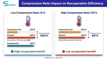
That is why recuperators show up most often on microturbines and other low-pressure-ratio cycles, where the temperature difference still justifies the added pressure drop and hardware.
Applications and Benefits of Gas Turbine Recuperators
Microturbines and Small-Scale Power Generation
Recuperators transform microturbine economics. These compact systems (typically under 1 MW) use single-stage compressors with low pressure ratios, creating ideal conditions for waste heat recovery.
Efficiency Transformation: Peer-reviewed research from 2017 documents that typical micro-gas-turbine electrical efficiency ranges from 16-20% without recuperation but rises to approximately 30% with recuperation. That near-doubling cuts fuel costs and shortens payback periods.
Key Microturbine Applications:
- Distributed generation: On-site power for commercial buildings, hospitals, and data centers
- Combined heat and power (CHP): Simultaneous electricity and thermal energy for industrial facilities
- Remote installations: Oil and gas wellheads, telecommunications towers, and island communities
- Grid support: Peak shaving, demand response, and backup power
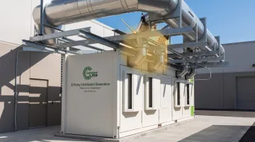
Capstone's microturbine line integrates an annular recuperator into every model, demonstrating how recuperation has become standard rather than optional in this market segment.
Industrial Gas Turbines
Mid-scale industrial turbines benefit from recuperation when they run continuous, high-utilization duty cycles and fuel cost is a primary concern.
Target Applications:
- Oil and gas compression: Pipeline and storage facilities running 24/7
- Process industries: Chemical plants, refineries, and manufacturing with steady thermal loads
- Mechanical drive systems: Pumps, compressors, and generators in continuous operation
Recuperators in these settings typically deliver 15-20% thermal efficiency improvements when matched to appropriate compression ratios and operating conditions. The decision hinges on capital cost versus fuel savings over the expected equipment lifetime.
Aerospace and Marine Propulsion
Recuperators appear in specialized aerospace and marine applications where efficiency outweighs the traditional gas turbine advantages of compactness and low weight.
Examples:
- Auxiliary power units (APUs): Aircraft ground power and environmental control systems
- Marine gas turbines: Naval vessels and commercial ships where fuel cost and range matter
- Unmanned aerial vehicles (UAVs): Extended-endurance missions where fuel weight drives performance
These applications remain niche compared to power generation, as most propulsion systems prioritize thrust-to-weight ratio over fuel economy.
Key Efficiency and Economic Benefits
Fuel Consumption Reduction: By preheating combustion air, recuperators reduce the fuel needed to reach target turbine inlet temperatures. For systems running thousands of hours annually, this translates to substantial operating cost savings.
Carbon Footprint: Lower fuel consumption directly reduces CO₂ emissions. Exact figures depend on fuel type, utilization, and baseline efficiency, but the outcome is straightforward: less fuel burned per kilowatt-hour generated.
Secondary Benefits:
- Lower exhaust temperatures: Reduces thermal signature and downstream equipment stress
- Improved part-load efficiency: Recuperation often maintains efficiency advantages across operating ranges
- Reduced cooling requirements: Less fuel combustion can simplify thermal management
Economic Reality: Recuperators can account for 25-30% of total microturbine system cost. A 2020 optimization study reported modeled payback periods of 147-153 days for optimized designs, though these figures depend heavily on fuel prices, operating hours, and installation specifics.
Always run project-specific economic analysis before committing to recuperation. Modeling recuperated cycles in simulation software makes fuel-savings and payback estimates far more reliable under your actual operating profile.
Design Considerations and Limitations
Pressure Drop Penalties
Every recuperator introduces flow resistance. Compressed air must push through narrow channels on the cold side; exhaust gas encounters resistance on the hot side. Both streams lose pressure, which the compressor and turbine must overcome.
Performance Targets: The 2017 review identifies relative pressure loss below 3% as a desirable target. A 2025 design study calculated 3.69% total pressure loss for an optimized plate configuration, so even strong designs can approach or slightly exceed that threshold.
System Impact: Pressure drop forces the compressor to work harder and robs the turbine of expansion potential. Excessive loss can erase recuperation's efficiency gains. Engineers balance channel size, flow velocity, and surface area to maximize heat transfer while minimizing resistance.
Material Temperature Limits
Recuperator materials must withstand continuous exposure to hot exhaust gases while maintaining structural integrity, resisting oxidation, and tolerating thermal cycling.
Material Boundaries (from 2017 review):
- Stainless steel: Practical application limit below 650°C
- Inconel (nickel-based superalloy): Extends capability to approximately 800°C
- Ceramics: Enable operation above 870°C in experimental designs
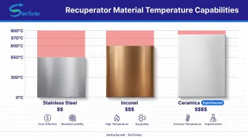
Most commercial recuperators use thin stainless steel foil for cost and manufacturability, constraining turbine exhaust temperatures. Advanced materials improve temperature tolerance but raise costs and fabrication complexity.
Fouling and Maintenance Challenges
Contaminant Accumulation: Exhaust streams carry combustion byproducts, particulates, and sometimes sulfur compounds or salts (especially in marine environments). Over time, deposits form on hot-side surfaces, insulating metal from gas flow and degrading heat transfer effectiveness.
Inspection Difficulties: Unlike turbine blades or combustors, recuperator internals are not easily accessible. Thousands of narrow parallel channels resist visual inspection and mechanical cleaning. Performance trending (monitoring temperature rise and pressure drop over time) becomes the primary diagnostic tool.
Maintenance Strategy:
- Monitor inlet and outlet temperatures continuously
- Track pressure drop across both sides
- Compare actual effectiveness to baseline
- Plan for periodic replacement rather than refurbishment in most designs
Size and Weight Trade-offs
Effective recuperators require substantial surface area, making them large and heavy relative to the turbine core. A 2025 study documented a recuperator core measuring 320 × 118 × 246 mm and weighing 15.068 kg for 117.62 kW heat duty. That is a significant addition to a compact microturbine package.
Design Consequences:
- Simple-cycle turbines stay more compact and keep higher power density without a recuperator
- Recuperated systems need a larger installation footprint
- Extra weight drives heavier skid design, structural support, and shipping costs
- Weight penalties limit use in aerospace and other weight-sensitive mobile roles
When to Use (and When NOT to Use) a Recuperator
Best Applications for Recuperators
Recuperators deliver the most value under these conditions:
- Low compression ratios (about 3-5:1): Large temperature differentials between compressed air and exhaust enable effective heat recovery. The 2017 review confirms this range as typical for recuperated microturbines.
- High-utilization duty cycles: Continuous or near-continuous operation maximizes fuel savings and shortens payback. Systems running 6,000+ hours annually usually justify the capital premium.
- Fuel-cost-sensitive applications: When fuel dominates lifecycle costs (remote sites, long-duration missions, or high energy prices), recuperation delivers measurable economic value.
When Recuperators Offer Minimal Benefit
Skip or deprioritize recuperation in these cases:
- High compression ratios (above 10:1, especially beyond 15:1): Compressor discharge temperatures approach exhaust temperatures, so the usable temperature differential shrinks. Large utility turbines at 16:1 or higher rarely justify recuperation.
- Highly transient duty cycles: Peaking plants, emergency backup generators, and intermittent-use systems log few hours annually. Fuel savings stay small, and the capital investment rarely pays back.
- Weight- and space-critical applications: In aircraft propulsion, mobile power, and compact installations, recuperator bulk and weight undercut core gas turbine advantages.
Economic Decision Framework
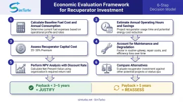
Before specifying a recuperator, evaluate:
- Fuel cost and annual consumption: Calculate baseline fuel spend
- Expected operating hours: Multiply annual hours by efficiency gain to estimate savings
- Recuperator capital cost: Often 25-30% of system cost
- Maintenance and degradation: Account for effectiveness loss over time and eventual replacement
- Discount rate and project life: Perform net present value analysis
- Alternative efficiency measures: Compare recuperation to combined-cycle, cogeneration, or higher-compression-ratio simple-cycle alternatives
Break-even Rule of Thumb: Projects with payback under 3-5 years typically justify recuperation. Longer paybacks require careful risk assessment and fuel-price forecasting.
Engineering Analysis and Optimization
Modeling Recuperator Performance
Engineers predict recuperator behavior using established heat exchanger analysis methods:
NTU-Effectiveness Approach: The Number of Transfer Units (NTU) method relates heat exchanger geometry, flow rates, and heat capacity to effectiveness. Engineers input proposed dimensions and flow conditions, then solve for expected thermal performance.
CFD Analysis: Computational fluid dynamics resolves three-dimensional flow distribution, temperature fields, and pressure losses within complex channel geometries. A 2021 study applied 3D fluid-solid coupled heat transfer modeling to five cross-wavy primary surface designs, documenting how CFD reveals flow maldistribution and localized hot spots that correlations miss.
Thermal Stress Analysis: After solving temperature fields with CFD, engineers export nodal temperatures to finite element analysis (FEA) tools. The 2021 study documented coupled thermal-structural analysis using 9,444 quadrilateral elements, calculating maximum stresses of 78.2 MPa near the air-outlet/gas-inlet junction and comparing results against material yield limits.
System-Level Integration and Cycle Analysis
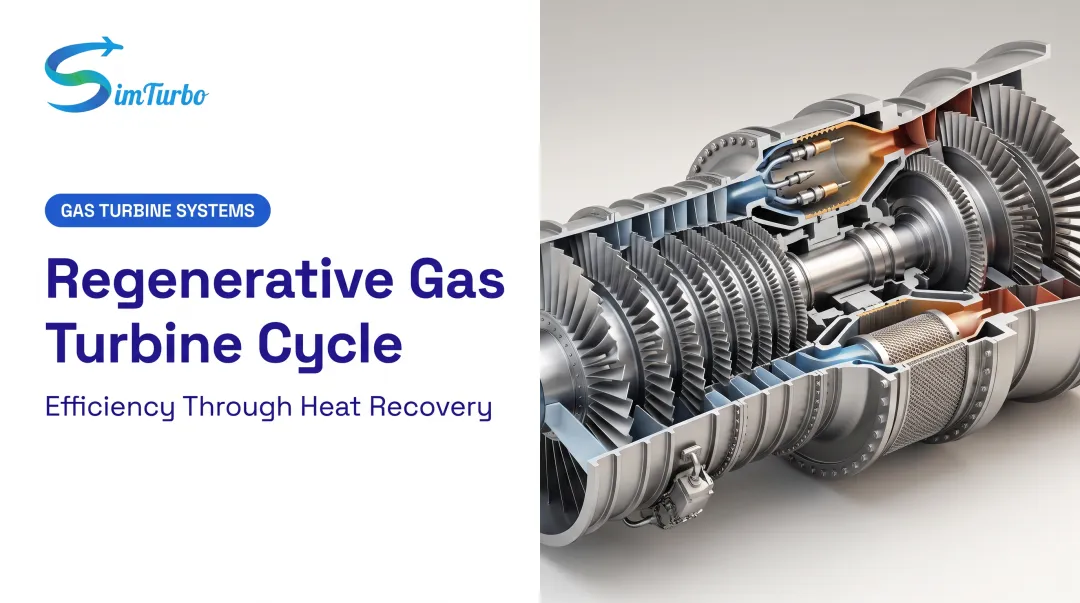
Recuperators interact with compressor matching, turbine work extraction, and control system responses. Specialized tools let engineers model those interactions inside complete thermodynamic cycles.
Component-Level Cycle Simulation: Platforms like SimTurbo allow engineers to build recuperated turbine architectures by adding and connecting components such as compressors, recuperators, combustors, and turbines in one integrated model.
That component-based approach shows how recuperator effectiveness, pressure drop, and heat transfer affect cycle efficiency, fuel consumption, and transient behavior across the operating range, instead of treating the engine as a single black-box calculation.
Optimization Considerations
Effectiveness vs. Pressure Drop: Higher effectiveness needs more surface area and longer flow paths, which raises pressure loss. Optimization algorithms search for geometry that maximizes net efficiency gain: total heat recovery minus parasitic losses.
Material Selection: Common material trade-offs include:
- Stainless steel: low cost and good manufacturability, but exhaust temperatures limited below 650°C
- Inconel: higher temperature capability at significantly higher cost
- Ceramic composites: potential above 870°C, still experimental
Choose materials from actual metal temperatures, oxidation environment, creep life, and budget.
Sizing for Duty Cycle: Design recuperators for the operating range where the system spends most time, not worst-case peak conditions. Oversizing for rare transients wastes capital and adds unnecessary weight.
Frequently Asked Questions
What is a gas turbine recuperator?
A gas turbine recuperator is a counterflow heat exchanger that recovers waste heat from turbine exhaust and transfers it to compressed air before combustion. This preheating reduces required fuel and improves overall cycle efficiency, particularly in low-compression-ratio systems.
How does a gas turbine recuperator differ from a heat exchanger?
A recuperator is a specific type of heat exchanger designed for gas-to-gas heat transfer within power cycles. Counterflow layout and cycle integration set it apart from general-purpose exchangers that may handle liquids, run in crossflow, or sit outside the power cycle.
What is the purpose of reheating in a gas turbine?
Reheating refers to intermediate combustion between turbine stages, adding energy mid-expansion to increase power output. This differs from recuperation, which recovers exhaust heat to preheat compressor discharge air. Reheating raises turbine inlet temperature; recuperation reduces fuel consumption.
What are the typical efficiency benefits of using a recuperator in a gas turbine?
Well-matched systems with low compression ratios typically see 15-20% thermal efficiency improvements. Microturbines see the largest gains, rising from about 16-20% electrical efficiency without recuperation to roughly 30% with it.
When should you NOT use a recuperator in a gas turbine?
Skip recuperation for high-compression-ratio turbines (above 10:1), where compressor-exit temperatures approach exhaust temperatures. Also skip them for intermittent-duty use, weight-critical installs such as aircraft propulsion, or projects where fuel cost is low relative to capital cost.
What are the maintenance requirements for gas turbine recuperators?
Recuperators are passive devices requiring no active maintenance but demand continuous performance monitoring. Track inlet/outlet temperatures and pressure drops to detect fouling. Unlike turbine internals, recuperator channels resist inspection and cleaning, so plan for eventual replacement rather than refurbishment in most commercial designs.