Introduction
When engineers talk about turbine simulators, they're rarely talking about the same technology. An aerospace engineer designing a jet engine, a wind-farm developer optimizing blade loads, and a power-plant operator training for emergency scenarios all work with tools called "turbine simulators"—but the physics, software, and workflows behind each are entirely different.
The confusion is real: gas turbine simulators focus on Brayton-cycle thermodynamics and compressor-turbine matching, wind turbine simulators emphasize aeroelastic coupling and wake effects, and steam turbine simulators model Rankine-cycle phase changes.
This guide breaks down those three main categories—what each does, who uses it, and which one fits your design, control, or training problem.
Key Takeaways
- Gas, wind, steam, and hydraulic turbine simulators each use different physics models and applications
- Real-time simulation enables HIL testing but does not replace physical certification
- Validated gas turbine models can hit design-point accuracy within 1%
- System-level tools cut engine-system simulation time by an estimated 55% across the product life cycle
- Use simulation for design, controls, failure modes, and training—then confirm with physical data
What is Turbine Simulation?
Turbine simulation uses computational models and software to replicate the behavior, performance, and operating conditions of turbine systems without building physical prototypes. NASA defines a gas-turbine simulation as a computer solution to a mathematical representation of the engine cycle, intended to mimic steady-state or dynamic behavior.
The same principle applies to wind, steam, and hydraulic turbines, but the physics, components, and validation approaches differ.
Core purposes:
- Reduce development costs by testing dangerous or expensive scenarios virtually
- Accelerate design cycles through rapid iteration and broader design-space exploration
- Optimize performance before manufacturing through parametric sweeps and transient analysis
- Validate control systems and protection logic in closed loop
Fundamental Components
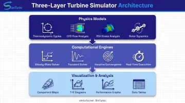
Every turbine simulator, regardless of type, combines three layers:
- Physics models: Thermodynamic cycles (Brayton for gas, Rankine for steam), fluid dynamics (CFD for detailed flow), structural mechanics (FEA for stress/deformation), and rotor dynamics
- Computational engines: Solvers for steady-state design points, dynamic transients, iterative convergence, and in some cases real-time execution
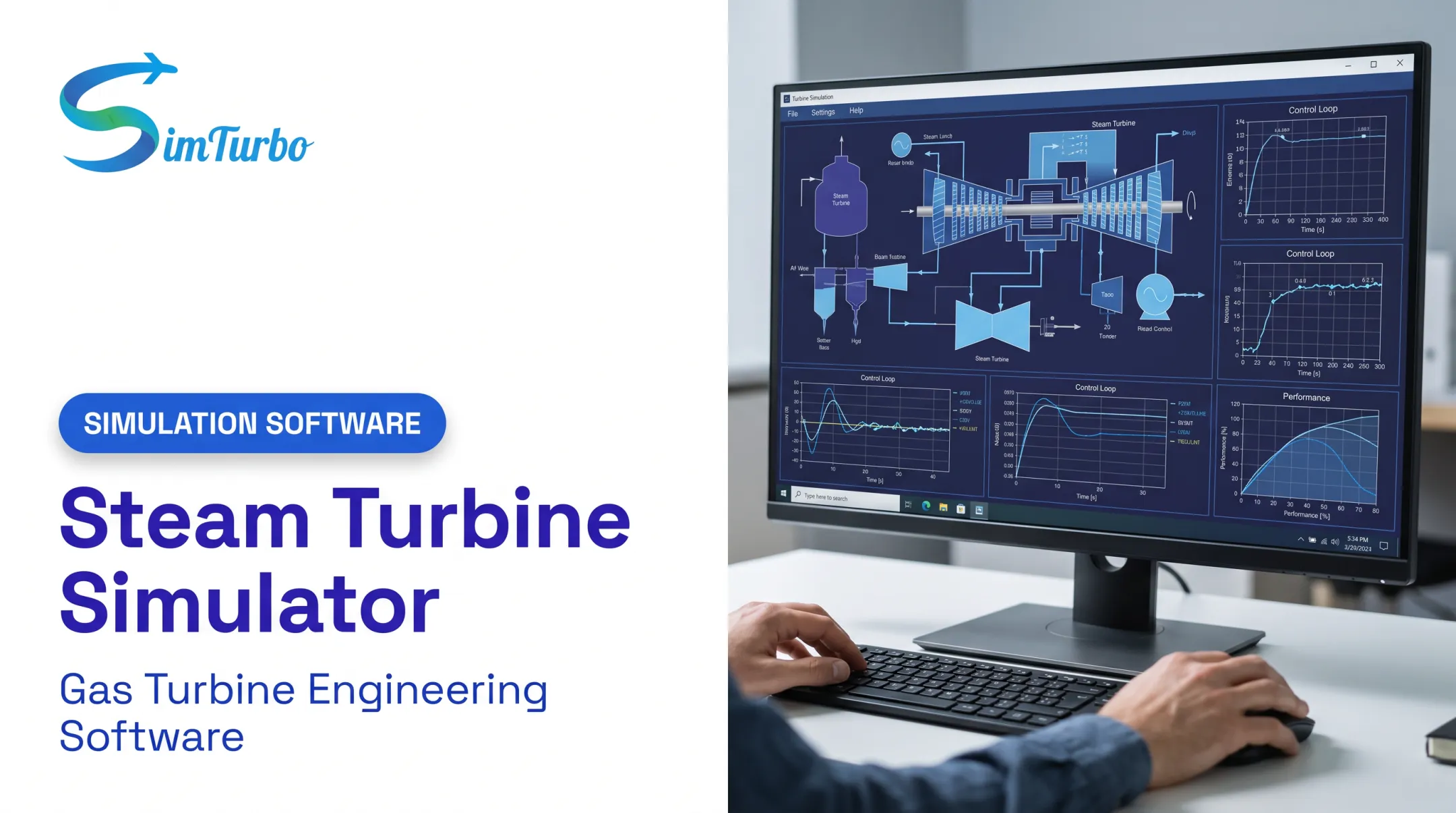
- Visualization and analysis: Component maps, T-S diagrams, time-history graphs, performance tables, and data export for post-processing
Evolution from Mathematical Models to Real-Time Hardware-in-the-Loop
NASA's 1993 review notes that gas-turbine simulations began about four decades earlier and migrated from analog to hybrid and then digital platforms. Modern simulation now supports:
- Object-oriented component libraries in environments like Simulink
- Real-time execution on standard PCs and dedicated HIL hardware
- Physical controller integration with simulated plant models
- Iterative multiphysics coupling between CFD, FEA, and system solvers
For example, NASA's 2023 HIL test coupled physical electrical machines with a real-time propulsion simulation and control logic running on a dSPACE SCALEXIO system.
Siemens Wind Power used NI real-time/FPGA hardware to test turbine-control software, running factory-acceptance testing for each software release and probing unusual situations in a lab environment.
How Simulation Complements Physical Testing
Simulation does not replace physical testing; it enables rapid iteration and broader design-space exploration before hardware commit. Physical data remain essential validation inputs: NASA performance maps may come from CFD, experiments, or generic maps. FAA certification guidance still specifies physical endurance and teardown testing for all turbine-engine classes, covering overtorque, calibration, and material behavior that computation alone cannot fully verify.
Types of Turbine Simulators
Gas Turbine Engine Simulators
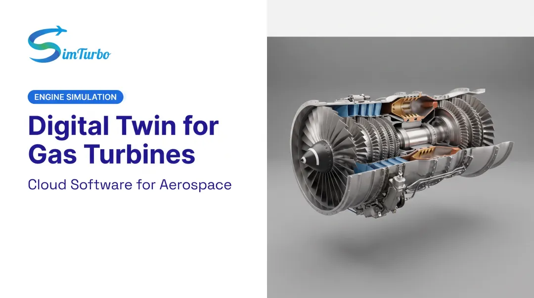
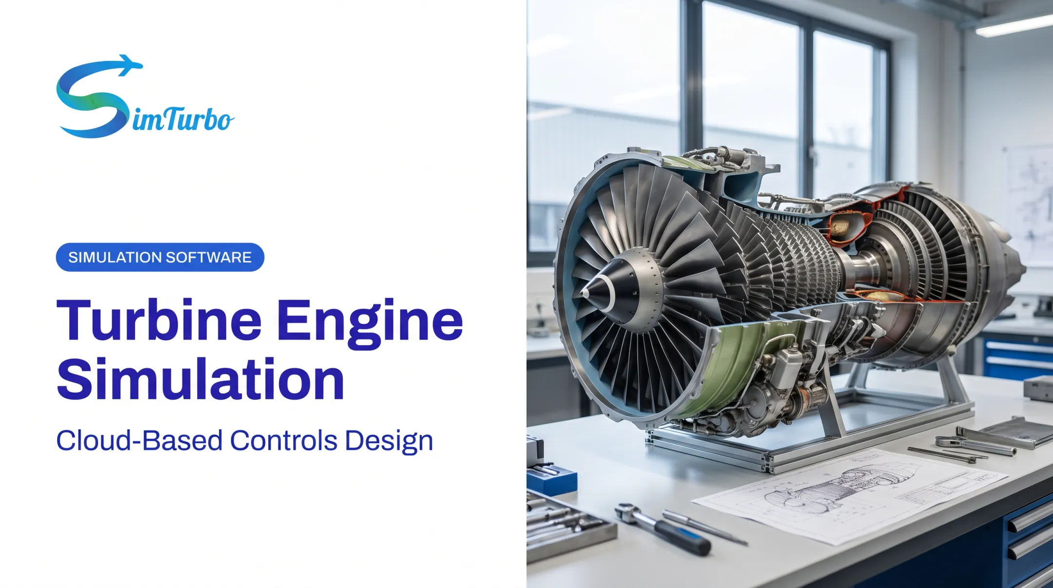
Gas turbine simulators model aircraft engines, marine propulsion, and power-generation turbines. They emphasize:
- Brayton-cycle thermodynamics: Compression, constant-pressure heat addition, expansion, and conservation of energy and momentum
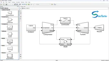
- Component-based architecture: Separate models for inlets, compressors, combustors, turbines, nozzles, and shafts, connected and solved iteratively
- Compressor-turbine matching: Map-based isentropic formulations, corrected mass flow, pressure ratio, and operating-point tracking
- Control system validation: PID logic, FADEC algorithms, fuel scheduling, and protection logic tested in closed loop
NASA's T-MATS toolbox provides open-source Simulink component libraries and iterative solvers for steady-state and transient gas-turbine simulation. Companies using NPSS estimated a 55% reduction in engine-system simulation time across the product life cycle. Commercial platforms such as SimTurbo add Windows-based, real-time component modeling and control-system design for aerospace and power-generation teams.
Typical users: Aerospace engineers, defense contractors, marine propulsion designers, power-plant controls teams, and university researchers.
Wind Turbine Simulators
Wind turbine simulators focus on aerodynamic blade design, structural mechanics, and wake effects in wind farms. Key modeling domains include:
- Coupled aeroelastic response: Aerodynamics, hydrodynamics, structural dynamics, and control/electrical systems solved together
- Rotor dynamics and blade loads: Dynamic stall, unsteady inflow, and fatigue analysis
- Wake effects: Deficit, advection, deflection, meandering, and merging in multi-turbine arrays
- Grid integration: Power-system dynamics, frequency response, and electrical behavior
OpenFAST, developed by NREL, serves research laboratories, industry, and academia with coupled aero-hydro-servo-elastic modeling. NREL researchers state that wind-turbine design requires thousands of simulations across inflow and control conditions to capture lifetime structural loads. Automated simulation is the practical way to cover that design space.
Typical users: Wind energy developers, renewable energy researchers, turbine manufacturers, and wind-farm operators.
Steam Turbine Simulators
Steam turbine simulators model power plants and industrial applications, emphasizing:
- Rankine-cycle heat balance: Expansion, condensation, superheat/reheat stages
- Phase changes and two-phase flow: Steam properties, moisture content, and efficiency impacts
- Power-cycle analysis: Combined-cycle integration, bottoming-cycle transients, and startup/shutdown behavior
- Efficiency optimization: Heat-rate studies, load-ramp response, and part-load performance
GE's high-fidelity simulators use the actual plant control platform for standard and emergency-scenario practice and pre-deployment change review.
Typical users: Combined-cycle designers, plant-control teams, operators, and nuclear-training organizations.
Hydraulic Turbine Simulators
Hydraulic turbine simulators focus on hydroelectric applications:
- Water-flow CFD: Detailed three-dimensional flow through runners, draft tubes, and passages
- Cavitation modeling: Unsteady phenomena, pressure distribution, and erosion risk
- Power generation optimization: Efficiency mapping, head-flow relationships, and governor response
- Grid-operation studies: Frequency control, balancing authority support, and spinning reserve
CFD studies of a 1 MW hydraulic turbine reported maximum 1.7% power deviation from field tests under baseline conditions, though free-surface configurations produced substantially longer runs and higher deviations.
Typical users: Hydropower project operators, transmission authorities, turbine manufacturers, and consultants.
Gas Turbine Simulation Explained
Gas turbines present unique simulation challenges:
- High temperatures: combustion studies report gas temperatures above 3,000°F / 1,649°C
- Transient behavior across startup and throttle changes
- Component interdependencies that require iterative solutions
- Control system complexity with protection logic and gain scheduling
Component-Based Modeling Approach
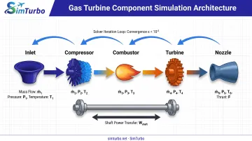
Rather than treating the engine as a black box, modern gas-turbine simulators model each component individually. T-MATS separately models:
- Ambient conditions, inlets, and ducts
- Compressors (using map-based isentropic formulations)
- Burners/combustors with heat addition
- Turbines (also map-based)
- Nozzles and exhaust paths
- Shafts with rotational dynamics
- Splitters, valves, and bleed ports
Components are connected, and the solver iterates to satisfy mass, energy, and momentum conservation across the entire cycle. Volume packing accounts for fluid storage in transient scenarios, while heat transfer between gas and metal surfaces captures thermal inertia.
Real-Time Simulation and Hardware-in-the-Loop
Those component models often need to run fast enough for control testing. Real-time simulation means calculations and I/O meet strict wall-clock deadlines, so a physical controller can interact with the simulated turbine. NASA implemented this on dSPACE SCALEXIO hardware, while Siemens used real-time processors plus FPGA-based sensor/protocol interfaces.
HIL supports:
- Control software factory-acceptance testing
- Sensor-failure and fault-injection scenarios
- Emergency-procedure validation
- Gain-scheduling verification across the flight envelope
- Pre-deployment testing of algorithm changes
Real-time HIL does not replace certification. It verifies that control hardware behaves correctly when coupled to a high-fidelity plant model.
Validation Approaches
Validation correlates simulation results with physical test data. NASA's J85 model reported:
- Thrust error of 0.3%
- SFC error of 0.01%
- Turbine-inlet-temperature error of 0.14%
- All listed design-point parameters below 1%
When T-MATS was compared with NPSS, the two tools differed by less than 0.5% overall, including a 0.15% thrust difference.
Accuracy depends on model fidelity, performance-map provenance (CFD, test, or generic), operating point, and validation data quality. No universal industry tolerance exists. Each application requires case-specific benchmarking.
SimTurbo: Gas Turbine Simulation for Aerospace, Marine, and Power
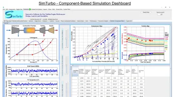
The same component-based, real-time, and validation principles show up in packaged tools. SimTurbo is a Windows-based platform from Controls Research LLC, built on patent-pending technology. It models engines component-by-component, runs in real time on standard PCs, and serves aerospace, marine, and power-generation work.
Key capabilities:
- Drag-and-drop design with inlets, compressors, combustors, turbines, nozzles, shafts, recuperators, and afterburners
- Real-time steady-state and transient runs with live T-S diagrams, compressor maps, and time-history graphs
- Built-in PID controllers, FADEC logic, and control-system validation tools
- J85-GE-21 validation within ±2% of NASA test data for thrust, flow rate, temperature, and TSFC
- Cloud access with a 30-day free trial, plus monthly ($59.99/mo), one-year ($599/yr), and lifetime ($5,999) licenses
- Educational pricing for universities, classrooms, and research labs
Supported configurations include single- and dual-spool turbojets, hybrid-electric concepts, and aero-derivative power-generation models. Engineers can run off-design and transient cases (startup, slam acceleration, surge, sensor failures), export results to CSV or Excel, and check external control laws against the plant model.
Contact (779) 390-4786 or pjhoffman@simturbo.net for trial access or educational programs.
Simulation Methodologies and Technologies
Offline vs. Real-Time Simulation
| Method | Primary Role | Execution Speed | Typical Application |
|---|---|---|---|
| Offline steady-state | Design-point and off-design thermodynamic analysis | Faster than real-time; steady models unchanged with time | Cycle optimization, component sizing |
| Offline dynamic | Time-varying startup, shutdown, throttle response | May exceed real-time; no wall-clock constraint | Control-law development, transient studies |
| Real-time HIL | Live I/O exchange with actual controller hardware | Exactly real-time; deterministic deadlines | Software factory-acceptance, fault injection |
Offline models dominate architecture and optimization work; real-time HIL prioritizes deterministic controller interaction.
Hardware-in-the-Loop (HIL) Simulation
HIL connects a physical controller (FADEC, SCADA system, or embedded processor) to a simulated turbine running on real-time hardware. The controller sends commands (fuel flow, valve position), receives sensor feedback (RPM, temperature, pressure), and executes protection logic exactly as it would on the real engine.
Requirements:
- Real-time computing (dSPACE, NI PXI, custom FPGA systems)
- I/O conditioning and signal interfaces matching physical sensors/actuators
- Model simplification to meet execution-time constraints
- Validation that the simplified model still represents critical dynamics
HIL is proven in both aerospace and power-generation gas turbine applications but remains a verification tool, not a substitute for physical endurance, calibration, or material testing.
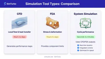
CFD and FEA Roles in Detailed Component Design
| Tool | Resolves | Computation Cost | System-Level Role |
|---|---|---|---|
| CFD | Local flow, heat transfer, pressure distribution, separation, mixing | High (hours to days per run) | Generates performance maps, validates loss models |
| FEA | Stress, deformation, thermomechanical response, fatigue | High (especially transient thermomechanical) | Provides component limits, validates structural assumptions |
| System simulation | Cycle performance, component matching, transient response | Low to moderate (seconds to minutes) | Uses CFD/FEA outputs as inputs; trades fidelity for speed |
An ASME turbine study used CFD for disk-cavity flow, FEA for thermomechanical response, and iterated both each transient step to reconcile surface temperature and heat flux. This coupled multiphysics approach prioritizes local fidelity over speed. System-level cycle tools enable broad design sweeps, but at lower resolution.
Applications and Benefits of Turbine Simulation
Key Applications
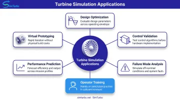
Turbine simulation shows up across design, validation, operations, and research:
- Design optimization: NASA uses engine models for design-point, off-design, transient, operability, and derivative-engine studies. Parametric sweeps across altitude, Mach number, throttle, and component efficiency surface performance peaks and operating limits.
- Control system validation: Siemens' HIL system runs factory-acceptance testing for each control-software release and rehearses unusual cases in the lab, catching integration errors before field deployment.
- Failure mode analysis: Teams can exercise compressor stall, sensor failures, fuel-system faults, and emergency shutdowns without risking hardware, and confirm protection logic responds and recovers safely.
- Operator training: GE's high-fidelity simulators use the actual plant control platform for standard and emergency drills so operators see abnormal conditions before production.
- Performance prediction: In the broader turbine industry, tools such as NREL's FAST.Farm model wake effects and reported generally good agreement with measured power and loads across multiple wind farms.
- Virtual prototyping: Engineers build and test engine variants—recuperated cycles, hybrid-electric concepts, and other advanced configurations—before committing to physical prototypes.
Cost and Time Benefits
Companies using NPSS for propulsion system simulation estimated a 55% reduction in engine-system simulation time across the product life cycle. Those gains came from faster architecture screening, cycle analysis, and control-law development.
Hard figures on fewer physical prototypes or shorter certification are scarce. Even so, early simulation narrows test scope and improves test planning by exposing problems before hardware is on the stand.
Educational Applications
Universities use turbine simulation for:
- Teaching turbomachinery principles and thermodynamic cycles
- Laboratory experiments and capstone projects
- Control-system design courses
- Graduate research on advanced propulsion concepts
Purdue's PETAL laboratory pairs computational analysis with measurement and experimental turbine testing, showing how simulation and physical validation work together in engineering education. Dedicated gas-turbine tools with classroom licensing—such as SimTurbo—make that same workflow practical for labs, capstone teams, and graduate research.
Frequently Asked Questions
What is the difference between a turbine simulator and turbine modeling software?
Simulators emphasize real-time execution, interactive operation, and live display updates for control testing and operator training. Modeling software often targets design-phase work such as steady-state cycle optimization, component sizing, and parametric sweeps, without real-time or live I/O constraints. Platforms like SimTurbo combine both offline design exploration and real-time transient control validation.
Which type of turbine simulator do I need for aerospace applications?
Aerospace applications require gas turbine engine simulators focused on jet engines, turboprops, or auxiliary power units. These tools model Brayton-cycle thermodynamics, compressor-turbine matching, combustion, transient response, and control systems. Platforms like T-MATS, NPSS, and SimTurbo specialize in this domain, with validation against engines like the J85 or Boeing 747 APU.
Can turbine simulators replace physical testing entirely?
No. Simulation cuts test scope and sharpens test planning, but it does not replace regulatory or material-validation work. FAA AC 33.87-1A still calls for overtorque, calibration, endurance, and teardown tests, and physical runs remain essential for bird ingestion, extreme temperatures, and certification.
What is Hardware-in-the-Loop (HIL) simulation for turbines?
HIL simulation runs the turbine plant model on real-time hardware while a physical controller (FADEC, embedded unit, or PLC) connects over live I/O. The controller commands the model and reads sensor feedback as it would on the real engine, so you can run factory-acceptance tests, fault injection, and emergency procedures without operating the turbine.
How accurate are turbine simulators compared to real turbine performance?
Accuracy depends on model fidelity, validation data, and operating point. Published benchmarks include T-MATS vs. NPSS under 0.5% overall difference and NASA’s J85 design-point model under 1% error on listed parameters. There is no universal ±2–5% industry tolerance; validate against physical test data and expect accuracy to fall off outside that envelope.
What software platforms are available for turbine simulation?
| Category | Representative Platforms |
|---|---|
| Gas-system thermodynamics | NASA T-MATS (Simulink, open-source), NPSS (nonlinear propulsion/system integration), GasTurb (graphical modeling), SimTurbo (Windows GUI, cloud, real-time) |
| Wind aeroelastic/system | OpenFAST (NREL, coupled aero-hydro-servo-elastic), DNV Bladed (onshore/offshore aeroelastic design) |
| Steam/plant-cycle | Rankine-cycle and two-phase system models; EBSILON (steam turbine/general expander), GE high-fidelity plant simulators |
| Hydraulic | CFD and system-dynamics platforms for water passages, runners, cavitation, efficiency, and grid-operation studies |
Choose by turbine type and need: design analysis, real-time controls, training, or detailed CFD. For gas turbine work, SimTurbo offers a 30-day free trial; call (779) 390-4786 or email pjhoffman@simturbo.net to compare fit for your workflow.