Introduction
Engineers, students, and propulsion professionals in automotive, aerospace, marine, and power systems meet the combustion cycle constantly. Valve timing, pressure-temperature relationships, and thermodynamic efficiency still trip people up in design and troubleshooting.
The combustion cycle is the thermodynamic sequence of intake, compression, power, and exhaust that converts fuel into mechanical energy in internal combustion engines. How each stage behaves, and what drives cycle performance, directly affects engine design, tuning, and diagnostics.
This article covers the four-stroke cycle’s operational mechanics, the engineering factors that shape performance, and where those details matter in real propulsion and power-generation work.
Key Takeaways
- The combustion cycle repeats four distinct strokes over two crankshaft revolutions (720 degrees), converting fuel and air into mechanical work
- Valve timing, compression ratio, air-fuel mix, and ignition timing drive efficiency, power, and durability
- Abnormal combustion (detonation and pre-ignition) can destroy an engine if left undiagnosed
- Cycle knowledge underpins engine design, performance tuning, troubleshooting, and control development
What Is the Combustion Cycle?
The combustion cycle is the thermodynamic process that turns chemical energy in fuel into mechanical work. In an internal combustion engine, that happens through a controlled sequence of intake, compression, combustion, and exhaust.
The goal is simple: extract as much useful work as possible from each burn while limiting waste heat and keeping the hardware reliable over repeated cycles.
The four-stroke combustion cycle usually means the Otto cycle (spark ignition) or the Diesel cycle (compression ignition). Both differ from two-stroke, rotary, and gas turbine Brayton cycles, though the underlying thermodynamics still overlap.
According to NASA's Glenn Research Center, a four-stroke engine completes four piston movements (intake, compression, power, and exhaust) before the sequence repeats, over two full crankshaft revolutions (720 degrees).
Core Cycle Elements
- Prepare the air-fuel mixture with a carburetor or fuel injection
- Operate valves in sync with piston position
- Time ignition to maximize combustion efficiency
- Expel exhaust gas so the next intake stroke can begin
Why the Combustion Cycle Is Critical in Engine Design
The four-stroke cycle is used across automotive, aerospace, marine, and power generation systems because it delivers thermal efficiencies of 30–40%, smooth power delivery, and flexibility across fuels: gasoline, diesel, and aviation fuel.
Toyota has shown 38% maximum thermal efficiency in gasoline engines with 13.5:1 compression ratios, cooled EGR, and variable valve timing. Diesel engines have reached 34–44% brake thermal efficiency over decades of development.
Engineering Challenges the Cycle Addresses
- Consistent power output across varying load and speed conditions
- Fuel economy through efficient energy extraction from combustion
- Emissions control via complete combustion and optimized air-fuel ratios
- Mechanical durability over millions of cycles and extreme temperatures
- Wide operating range including altitude, ambient temperature, and fuel type variations
Consequences of Poor Cycle Understanding
Weak grasp of cycle mechanics shows up quickly in the field:
- Incomplete combustion leading to power loss and carbon buildup
- Detonation (uncontrolled autoignition after the spark) causing piston damage, broken ring lands, and eroded valves, as documented by the FAA
- Pre-ignition (ignition before the timed spark) due to hot spots or deposits
- Valve timing errors reducing volumetric efficiency and power output
- Poor fuel-air mixing creating rich or lean conditions that foul spark plugs and increase emissions
Engineers who know the cycle can diagnose performance issues and tune designs for the job at hand. That fluency is also common ground for FAA certification in aerospace and related automotive work.
How the Combustion Cycle Works (Conceptual Flow)
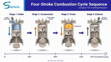
The combustion cycle repeats four stages in order. The cylinder draws in air and fuel, compresses the charge, ignites it so expansion drives the piston down on the power stroke, then expels exhaust so the next cycle can start.
Process Inputs:
- Atmospheric air mixed with fuel (controlled by carburetor or fuel injection)
- Spark or compression ignition (depending on engine type)
- Mechanical valve operation synchronized with piston movement
Process Controls:
- Valve timing regulates intake and exhaust valve opening/closing relative to piston position
- Ignition timing determines when the spark plug fires relative to crankshaft position
- Fuel metering adjusts the air-fuel ratio for current operating conditions
Intake Stroke (Stage 1)
The intake valve opens as the piston moves from top dead center (TDC) to bottom dead center (BDC), creating a vacuum that draws an air-fuel mixture into the cylinder. Proper valve timing and intake manifold design maximize volumetric efficiency—the ratio of actual air mass inducted to theoretical maximum.
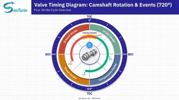
The FAA notes that overlap (brief periods when both intake and exhaust valves are open) uses gas momentum to improve charge entry and exhaust removal, though excessive overlap can reduce low-speed power.
Compression Stroke (Stage 2)
Both valves close as the piston moves from BDC back to TDC, compressing the air-fuel mixture. MIT defines compression ratio as maximum cylinder volume divided by minimum cylinder volume (V₁/V₂).
That compression raises pressure and temperature. Thermal efficiency follows the ideal Otto cycle equation: η = 1 - 1/r^(γ-1), where r is compression ratio and γ is the specific heat ratio.
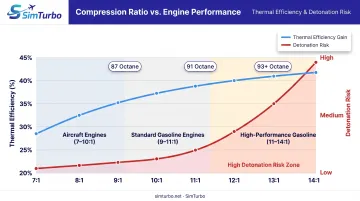
Higher compression ratios improve efficiency but increase risk of detonation. For example, Lycoming O-360 aircraft engines use compression ratios ranging from 7.2:1 to 10.0:1 depending on fuel octane and application.
Power Stroke (Stage 3)
Near TDC, the spark plug ignites the compressed mixture (or compression heat ignites diesel fuel). Rapid combustion forces the piston from TDC to BDC and converts chemical energy into mechanical work on the crankshaft.
The FAA reports normal flame travel at approximately 100 feet per second, with maximum pressure just after TDC for optimal power extraction.
Ignition timing must be precise: too early causes pre-ignition and excessive cylinder pressure; too late cuts power because peak pressure arrives too far down the stroke. Lycoming engines specify spark timing between 20 and 25 degrees before top dead center, depending on the model.
Exhaust Stroke (Stage 4)
The exhaust valve opens as the piston moves from BDC back to TDC, expelling combustion byproducts (CO₂, H₂O, NOₓ, and unburned hydrocarbons) through the exhaust manifold. Efficient scavenging clears the cylinder for the next intake stroke and limits dilution of the fresh charge.
With the exhaust stroke complete, the cylinder is ready to repeat the cycle from intake.
Where the Combustion Cycle Is Applied
The four-stroke cycle shows up in the hardware you run, the design choices you make, and the faults you diagnose.
Systems and Equipment
The four-stroke combustion cycle powers:
- Automotive engines – cars, trucks, and motorcycles
- Aircraft piston engines – Lycoming O/IO/HIO/TIO-360 series, Rotax 912 iS four-cylinder engines
- Marine propulsion – Mercury FourStroke outboard motors
- Stationary power equipment – generators (Cummins 4BT3.9 diesel), pumps, and compressors
Critical Lifecycle Points
Cycle knowledge matters most at these points:
Design and prototyping:
- Selecting compression ratios based on fuel octane requirements
- Determining valve timing and overlap strategies
- Specifying ignition advance curves for different operating conditions
Performance tuning and modification:
- Adjusting ignition timing for maximum power or efficiency
- Upgrading intake and exhaust systems to improve volumetric efficiency
- Recalibrating fuel delivery for forced-induction applications
Maintenance and troubleshooting:
- Diagnosing misfires and rough running
- Identifying valve wear or incorrect clearances
- Detecting carbon deposits that affect compression
Educational training:
- Teaching thermodynamics and control systems
- Demonstrating real-time cycle behavior through simulation
- Preparing engineers for certification exams
Analysis Triggers
Common triggers for cycle analysis:
- Performance degradation (loss of power, rough idling)
- Abnormal combustion events (knocking, pre-ignition)
- Emissions compliance testing
- Fuel efficiency optimization for new operating conditions (altitude, temperature, fuel type)
Key Factors That Affect the Combustion Process
Compression Ratio
Higher compression ratios raise thermal efficiency but need higher-octane fuel to prevent detonation. MIT's thermodynamics course shows ideal Otto efficiency climbing with compression ratio.
Real engines still have to balance that gain against fuel grade and mechanical stress. Toyota's 1.3 L gasoline engine, for example, reaches 38% thermal efficiency at 13.5:1 compression with cooled EGR and variable valve timing.
Valve Timing and Overlap
Intake and exhaust valve opening and closing points shape volumetric efficiency, power delivery, and exhaust scavenging. A 2009 study found that variable valve timing (VVT) cut pumping loss and specific fuel consumption at part load.
Timing strategy also shifts with RPM:
- Early intake-valve closing improves low-speed torque
- Late intake-valve closing supports high-speed power
The FAA warns that incorrect valve clearance changes the designed overlap period, which lowers efficiency and can cause valve-piston contact at high RPM.
Air-Fuel Ratio
The FAA documents a combustible gasoline range of 8:1 to 16:1 by mass, with about 12:1 needed for maximum power in aircraft engines. Mixture strength then trades efficiency against durability:
- Leaner mixtures: Better fuel efficiency, but higher risk of overheating, detonation, backfiring, or stoppage
- Richer mixtures (about 12:1 or richer at full power): Extra cooling and detonation margin, but more fuel use, emissions, carbon deposits, and plug fouling if left rich at idle
Ignition Timing
The spark must fire before TDC so the flame can develop while the mixture is still being compressed. Timing errors cut power or stress hardware:
- Late ignition: Peak pressure arrives too far down the stroke, so the engine loses power (FAA)
- Early ignition: Pre-ignition and excessive cylinder pressure that can damage pistons
Modern ECUs trim timing from speed, load, temperature, and knock-sensor feedback. Lycoming's model-specific data places typical spark timing between 20 and 25 degrees BTDC, depending on compression ratio and fuel grade.
Operating Temperature and Pressure
Cylinder head temperature, ambient air density, and altitude change mixture density and burn speed. The FAA notes that air density drops with pressure as altitude rises, so carbureted mixtures grow richer unless the pilot or system compensates—one reason altitude and inlet conditions belong in any combustion setup check.
Common Issues and Misconceptions
"All Four Strokes Happen Simultaneously"
In reality, each stroke is a distinct 180-degree piston movement. NASA documents that one complete cycle takes two full crankshaft revolutions (720 degrees). Intake occurs during the first half-revolution, compression during the second, power during the third, and exhaust during the fourth.
Compression Ratio vs. Boost Pressure Confusion
Compression ratio is a fixed geometric property: cylinder volume at BDC divided by volume at TDC.
Boost pressure (from turbochargers or superchargers) increases intake manifold pressure to force more air into the cylinder. That raises effective compression but does not change the geometric compression ratio.
"More Compression Always Equals More Power"
Excessively high compression can cause detonation, the spontaneous combustion of the unburned charge ahead of the normal flame front. The FAA reports that detonation produces extremely rapid pressure rise and can burn through pistons, break ring lands, or erode valves and heads. Optimal compression depends on fuel octane rating, ignition timing, and engine cooling capacity.
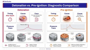
Detonation vs. Pre-Ignition
The FAA distinguishes these failure modes:
- Detonation occurs after the timed spark, when end gas autoignites ahead of the advancing flame front
- Pre-ignition occurs before the timed spark, typically caused by hot spots, carbon deposits, or overheated spark plugs
Both damage engines but require different diagnostic and corrective approaches.
When Understanding the Cycle Matters Most
You do not need deep cycle theory for every task. It matters most when design choices, tuning, diagnostics, or controls depend on what happens inside each stroke.
When Detailed Knowledge Is Less Critical
- Routine vehicle operation by non-technical users
- Basic maintenance tasks (oil changes, filter replacements, tire rotation)
- Applications where engine performance is already optimized and stable
When Cycle Understanding Becomes Essential
Engine design and simulation:
Compression ratios, valve timing, and combustion phasing drive efficiency, emissions, and power. FAA certification standards require reciprocating-engine operating theory, performance, maintenance, and troubleshooting knowledge. Simulation lets teams test those variables in real time before cutting hardware.
Performance tuning and racing:
Ignition timing, compression, and fuel delivery all reshape combustion behavior. Get them wrong and detonation or pre-ignition can destroy an engine within seconds under high load.
Troubleshooting abnormal combustion:
Detonation, misfires, and valve failures only make sense against normal cycle behavior. Distinguishing detonation (post-spark autoignition) from pre-ignition (pre-spark ignition) tells you whether to fix octane, cooling, or hot spots.
Control system development:
Modern engines use real-time combustion feedback to adjust timing, fuel injection, and valve phasing. Effective control algorithms depend on the links between pressure, temperature, and piston position across the cycle.
Conclusion
The combustion cycle is the four-stage thermodynamic process (intake, compression, power, exhaust) that converts fuel into mechanical work in internal combustion engines. It underpins automotive, aerospace, marine, and power generation systems.
Understanding each stage enables engineers to optimize performance, diagnose failures, and design more efficient engines. The 30–44% thermal efficiency range achieved by modern engines reflects decades of refinement in valve timing, compression ratios, fuel delivery, and combustion control.
Applying the cycle correctly matters more than memorizing the four stages. Set valve timing, ignition timing, and compression ratio for the application. Catch abnormal combustion early, and use thermodynamic fundamentals when you design or troubleshoot.
Frequently Asked Questions
What are the four stages of combustion?
The four stages are intake, compression, power, and exhaust: draw in the air-fuel mixture, compress it, ignite it to drive the piston down, then expel the burned gases. In a four-stroke engine, each stage is one piston stroke, and the full cycle takes two crankshaft revolutions (720 degrees).
What are the three phases of combustion?
Within the power stroke, combustion has three phases: ignition delay (spark to flame start), flame propagation (burning across the cylinder at about 100 feet per second), and final combustion (full fuel oxidation). These phases are not the same as the four mechanical strokes.
How does combustion cycle efficiency affect engine performance?
Higher cycle efficiency converts more fuel energy into work, which raises power, improves fuel economy, and cuts waste heat. It depends on compression ratio (ideal Otto equation), valve timing, complete combustion, and low friction—Toyota’s 38% thermal-efficiency gasoline engine shows the real-world payoff.
What is the difference between Otto cycle and Brayton cycle?
The Otto cycle (used in piston engines) involves intermittent combustion at constant volume, with discrete intake, compression, power, and exhaust strokes. The Brayton cycle (used in gas turbines) involves continuous combustion at constant pressure through compressor, combustor, and turbine stages. Both are thermodynamic cycles but apply to different engine architectures.
Why is valve timing important in combustion cycles?
Valve timing controls when intake and exhaust valves open and close relative to piston position. Proper timing maximizes cylinder filling (volumetric efficiency), ensures complete exhaust scavenging, and prevents valve-piston collisions at high RPM. Variable valve timing optimizes performance across different engine speeds and loads by adjusting overlap and valve duration.
What causes incomplete combustion in engines?
Common causes include a rich or lean air-fuel ratio, low compression, poor atomization, carbon deposits, and incorrect ignition timing. The FAA notes that extreme idle mixtures often leave unburned fuel, cutting power and fouling plugs with carbon.