Introduction
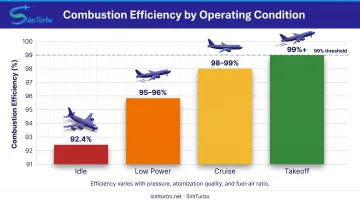
In aerospace, marine, and power generation, combustion efficiency determines whether fuel dollars convert into thrust and megawatts—or drift away as unburned hydrocarbons and carbon monoxide. Modern aircraft gas-turbine combustors exceed 99% combustion efficiency under intended operating conditions, converting nearly every molecule of fuel into usable heat. Yet that figure masks a critical reality: at idle, combustor pressure drops, atomization quality declines, and efficiency can fall to 92.4% or lower, wasting fuel and spiking emissions.
The stakes are substantial. Poor combustion efficiency:
- Cuts power output
- Raises fuel consumption
- Elevates CO and unburned-hydrocarbon emissions
For power plants chasing 60%+ combined-cycle efficiency or airlines managing narrow margins, even one percentage point of combustion loss matters.
This article covers how gas turbines reach near-complete fuel burn, what drives efficiency swings across operating conditions, and how engineers use engine simulation to tune combustion parameters before physical testing.
Key Takeaways
- Aircraft combustors exceed 99% efficiency at design point but drop sharply at idle
- Combustion efficiency tracks fuel-to-heat conversion; thermal efficiency tracks work output
- CO and unburned hydrocarbons signal incomplete combustion and efficiency loss
- Fuel-air ratio, pressure, atomization, and flame stability drive combustion completeness
Understanding Gas Turbine Combustion Efficiency
Definition and Measurement
Combustion efficiency measures how completely fuel releases its chemical energy as heat inside the combustion chamber. NASA defines the burner energy balance as:
(1+f)ht4 = ht3 + f·ηb·Q
Where:
f= fuel-to-air mass ratioht3andht4= combustor inlet and exit total enthalpiesQ= fuel lower heating valueηb= combustion efficiency
Rearranging gives ηb = [(1+f)ht4 - ht3] / (f·Q). This efficiency accounts only for the Brayton cycle's heat-addition process, not compressor work, turbine losses, or mechanical inefficiencies.
Benchmarks Across Operating Conditions
The National Academies reports that aircraft gas-turbine combustion systems exceed 99% efficiency under intended conditions. NASA testing of small-turbine combustors at simulated takeoff consistently exceeded 99% across multiple configurations.
At idle, the picture changes. A reverse-flow combustor tested under those conditions achieved only 92.4% efficiency, driven by poor fuel atomization and low combustor pressure.
Any combustion efficiency percentage must specify load, pressure, fuel-air ratio, and design. A universal "98–99.5%" band does not reflect real-world idle or low-pressure operation.
Combustion vs. Thermal Efficiency
- Combustion efficiency: Fraction of fuel chemical energy converted to combustor heat addition
- Thermal efficiency: Fraction of fuel energy converted to useful shaft or electrical output
High combustion efficiency is necessary but not sufficient for high thermal efficiency. A gas turbine with 99% combustion efficiency and 35% thermal efficiency still converts only 35% of fuel energy into work. The remaining 64% leaves largely as exhaust heat.
Relationship to Emissions
That gap shows up in the exhaust as well. CO and unburned hydrocarbons (UHC) are fuel energy that never fully oxidized. NASA's emissions-based efficiency method is:
ηb = 100 - (HC_EI / 10) - (CO_EI / 42.5) percent
Where emission indices (EI) are grams of pollutant per kilogram of fuel. A CO emission index of 42.5 or a hydrocarbon index of 10 each represents approximately one percentage point of combustion inefficiency.
EPA data confirms the same pattern in the field: stationary gas turbines show higher CO and UHC at lower loads, consistent with declining combustion efficiency.
How Gas Turbine Components Impact Combustion Efficiency
Combustion efficiency depends on how the compressor, combustor, and turbine work together. Each sets the pressure, mixing, and temperature conditions that determine how completely fuel burns.
Compressor Role
The compressor delivers high-pressure, high-temperature air to the combustor. NASA swirl-can tests showed that combustion efficiency generally increased with combustor pressure. In a separate reverse-flow combustor, efficiency fell sharply below a compressor pressure ratio of 8.5:1 at fixed fuel-air ratio. That threshold is test-specific and cannot be generalized.
Higher compression also improves:
- Air temperature entering the combustor, accelerating reaction rates
- Air density, shortening required residence time for complete combustion
- Atomization energy available through higher fuel-injection pressure differentials
Combustion Chamber Design
Three Major Architectures:
| Type | Characteristics | Trade-offs |
|---|---|---|
| Annular | Single continuous chamber around engine centerline | Compact, low pressure loss, uniform exit temperature; complex manufacturing |
| Can | Multiple individual cylindrical chambers arranged around centerline | Easier to test and service; heavier, larger, more pressure loss |
| Can-Annular | Individual liners within an annular casing | Balance of serviceability and compactness; moderate pressure loss |
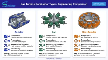
Research supports annular advantages in compactness, pressure loss, stability, and exit-temperature uniformity, but does not establish a universal numerical combustion-efficiency advantage over can or can-annular designs.
Three Functional Zones:
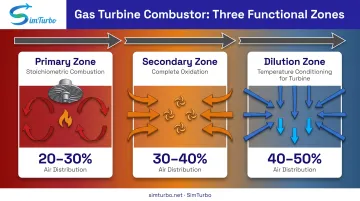
- Primary zone: High-temperature, near-stoichiometric region for rapid ignition and flame anchoring. Swirl-generated recirculation returns hot products to the flame front, improving stability and mixing.
- Secondary zone: Adds air to complete combustion by supplying oxygen for remaining fuel and mixing unburned pockets.
- Dilution zone: Adds air to reduce and shape combustor-exit temperature for turbine material limits. Its role is temperature conditioning, not additional heat release.
Fuel Injectors:
NASA testing demonstrated that poor low-flow atomization causes blowout and large efficiency loss. Changing injector count improved per-injector pressure drop, spray quality, and idle stability. Proper fuel atomization and air-fuel mixing are critical. Combustion efficiency depends more on physical atomization properties than on fuel chemistry alone.
Turbine Section Considerations
Higher turbine inlet temperature (TIT) improves Brayton-cycle thermal efficiency but creates a three-way trade-off:
- Thermal efficiency rises with higher TIT (more work per unit of heat addition)
- NOx emissions climb as flame temperature and residence time increase
- Cooling demands tighten against material temperature limits
NASA found that reducing liner cooling freed air for turbine cooling and enabled hotter turbine entry. However, higher TIT is a thermal-cycle and emissions trade-off, not evidence that combustion efficiency itself rises.
Calculating Combustion Efficiency in Gas Turbines
Engineers typically calculate combustor efficiency with thermodynamic energy balances, exhaust-species measurements, or simulation models. Each path trades measurement complexity for clearer insight into incomplete combustion.
Thermodynamic Method
- Measure fuel-air ratio
fand combustor inlet/exit total statesht3andht4 - Apply NASA's burner enthalpy equation:
ηb = [(1+f)ht4 - ht3] / (f·Q)
This approach depends on an accurate fuel heating value Q and reliable enthalpy data at the combustor boundaries.
Exhaust-Species Method
- Measure CO and unburned-hydrocarbon concentrations in the exhaust
- Convert those concentrations to emission indices (grams per kilogram of fuel)
- Apply the emissions-based formula:
ηb = 100 - (HC_EI / 10) - (CO_EI / 42.5)percent
The formula subtracts leftover HC and CO from complete combustion, so efficiency tracks incomplete-combustion products directly.
Equivalence Ratio Context
NASA defines equivalence ratio as:
φ = (fuel/O₂) / (fuel/O₂)stoich
φ < 1: Lean (excess air)φ = 1: Stoichiometric (perfect balance)φ > 1: Rich (excess fuel)
Overall engine equivalence ratio can differ substantially from local primary-zone values. Reporting only engine-wide fuel-air ratio can hide local extinction or rich pockets that reduce efficiency.
Simulation-Based Calculation
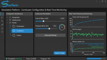
SimTurbo lets engineers model combustion efficiency across operating conditions before physical testing. Its component-based architecture treats the combustor as a distinct, configurable element in the gas turbine system.
Engineers can adjust fuel-air ratio, pressure, and control settings while monitoring:
- Turbine inlet temperature
- Fuel flow
- Thermodynamic cycle behavior in real time
The platform's J85-GE-21 simulation was validated against NASA test data within ±2% for thrust, flow rate, temperature, and thrust-specific fuel consumption, supporting pre-test combustion and efficiency assessment.
Key Factors Affecting Combustion Efficiency
Combustion efficiency depends on how completely fuel oxidizes inside the combustor. Three operating factors dominate that result: fuel-air ratio, combustor pressure and temperature, and ambient conditions.
Fuel-Air Ratio
NASA testing found that efficiency first increased with fuel-air ratio, then decreased when insufficient oxygen prevented complete combustion within the combustor length.
Too lean:
- Lowers flame temperature and reaction rate
- Eventually causes instability or blowout
- NASA's reverse-flow combustor lost efficiency as fuel flow dropped and atomization deteriorated
Too rich:
- Exhausts available oxygen before all fuel oxidizes
- Produces CO and unburned hydrocarbons (UHC)
- Wastes fuel energy
Optimal range: Near-stoichiometric in the primary zone, with secondary air added for completion.
Combustor Pressure and Temperature
- Higher pressure: Improved efficiency in NASA swirl-can tests; JT8D-17 idle runs also showed lower CO and UHC as pressure rose
- Higher temperature: Speeds reaction rates and combustion completeness, but raises NOx formation
In JT8D-17 idle-condition studies, higher compressor-inlet temperature reduced CO and UHC, while higher relative humidity increased them. Researchers did not establish a universal combustion-efficiency correction for temperature or humidity.
Ambient Conditions
Altitude, air temperature, and humidity change combustor inlet pressure, temperature, and oxygen density. Handle those effects through measured inlet conditions, residence time, and engine control schedules—not generic corrections.
SimTurbo supports analysis across altitude and ambient-condition changes, so engineers can examine off-design operation effects before testing.
Methods to Improve Gas Turbine Combustion Efficiency
Combustion efficiency rises when you cut the main loss paths: weak atomization, incomplete mixing, thermoacoustic instability, and slow design iteration. The methods below target each one.
Combustor Design Optimization
Fuel injector improvements:
- Match injector count and flow range to maintain adequate atomization across operating conditions
- NASA's 1978 test showed that fewer active injectors improved low-flow pressure drop and idle spray quality, while a larger injector set delivered 100% calculated efficiency at takeoff
Airflow staging:
- Use swirl for mixing and recirculation to anchor the flame
- Preserve secondary air for combustion completion
- Reserve dilution air for turbine-entry temperature shaping
Advanced Fuel Preparation
ASME research found combustion efficiency and lean blowout limits strongly affected by physical properties controlling atomization and spray evaporation, but only slightly dependent on fuel chemistry. This supports:
- Improved fuel atomization through better injector design and higher pressure differentials
- Optimized fuel spray patterns for better air-fuel mixing
However, no universal fuel-preheat efficiency gain was documented.
Active Combustion Control
NASA demonstrated pressure-feedback fuel modulation that cut thermoacoustic pressure amplitude from 0.84 to 0.05 psi (nearly 95%). Main-stage fuel-flow modulation of about ±8% of mean flow produced that suppression.
That level of damping enables real-time instability control and helps stop oscillations that damage hardware and erode efficiency. It is not, by itself, proof of a blanket gain in overall combustion efficiency.
Simulation and Virtual Prototyping
Before locking injector layout, staging, or control laws in hardware, teams can rehearse those choices in simulation. SimTurbo lets engineers run combustion scenarios and tune parameters virtually; its component-based palette supports fast synthesis and re-parameterization of combustors with the wider engine system (compressors, turbines, fuel path, sensors, and controls).
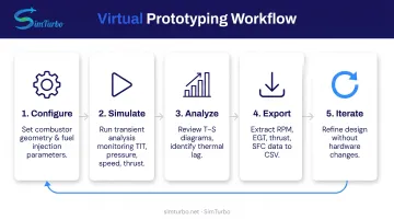
Virtual prototyping workflow:
- Configure combustor geometry and fuel-injection parameters
- Run transient simulations while monitoring turbine inlet temperature, pressure, speed, fuel flow, and thrust
- Examine Temperature-Entropy diagrams to validate heat addition and identify thermal lag
- Export transient results (RPM, EGT, thrust, specific fuel consumption) to CSV or Excel for further analysis
- Iterate combustor design and control parameters without physical hardware changes
Engineers can also model closed-loop control with PID and FADEC logic, including real-time fuel-rate, nozzle-area, and variable-stator-vane adjustments. Proving combustor and control changes in software first shortens test loops and lowers the cost of each design turn.
Real-World Applications and Efficiency Benchmarks
Aircraft Gas Turbines
- Modern aircraft combustors exceed 99% efficiency at intended high-power conditions
- NASA reverse-flow combustor reached 92.4% at idle in low-power operation
- Atomization quality and combustor pressure drive these results
Heavy-Duty Industrial Turbines
EPA materials describe high combustion efficiency at rated load, with CO and unburned hydrocarbons (UHC) rising as load falls. Primary literature does not set a universal class-wide percentage.
Measure site-specific performance rather than assume a generic band.
Combined-Cycle Context
Modern combined-cycle gas turbine (CCGT) plants can reach up to 64% thermal efficiency by recovering gas-turbine exhaust heat in a bottoming steam cycle. That number is overall plant thermal efficiency, not combustion efficiency.
Near-complete combustion is still required, but heat recovery, compressor and turbine performance, and plant losses set the 64% result.
Fuel-Type Considerations
ASME research shows stronger sensitivity to atomization and evaporation than to fuel chemistry. DOE-supported hydrogen work flags high flame speed and flashback risk but does not set a universal hydrogen combustion-efficiency percentage.
Avoid ranking natural gas, liquid distillate, and hydrogen blends without test-specific data. Fuel effects depend on injector design, combustor geometry, and operating conditions.
Frequently Asked Questions
How do you calculate gas turbine combustion efficiency?
NASA's thermodynamic method uses fuel-air ratio and combustor inlet/exit enthalpies: ηb = [(1+f)ht4 - ht3] / (f·Q). The exhaust-species method converts CO and UHC to emission indices: ηb = 100 - (HC_EI/10) - (CO_EI/42.5) percent.
What is the average combustion efficiency of a gas turbine?
Modern aircraft combustors exceed 99% efficiency at design conditions, but efficiency falls with load, pressure, and atomization quality. NASA testing recorded 92.4% at idle in a reverse-flow combustor—always cite operating conditions when reporting the figure.
Are gas turbines more efficient than diesel engines?
Simple-cycle gas turbines achieve 24–36% thermal efficiency (HHV) versus 30–42% for reciprocating engines. Combined-cycle plants can exceed 60% by recovering exhaust heat. Combustion efficiency itself is comparable at design conditions (both exceed 98%); system efficiency depends on configuration and heat recovery.
How does combustion efficiency affect gas turbine power output?
Lower combustion efficiency means less fuel energy becomes heat in the combustor. Holding turbine-inlet temperature and power requires burning more fuel, so each point of inefficiency raises fuel cost and cuts power per unit of fuel.
What role do simulation tools play in optimizing combustion efficiency?
Simulation platforms such as SimTurbo support virtual prototyping before physical tests. Engineers can vary fuel-air ratio, combustor design, and controls while tracking turbine inlet temperature, emissions, and transients—cutting cost and risk across operating conditions.