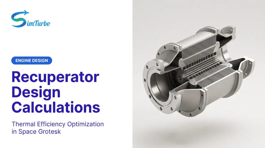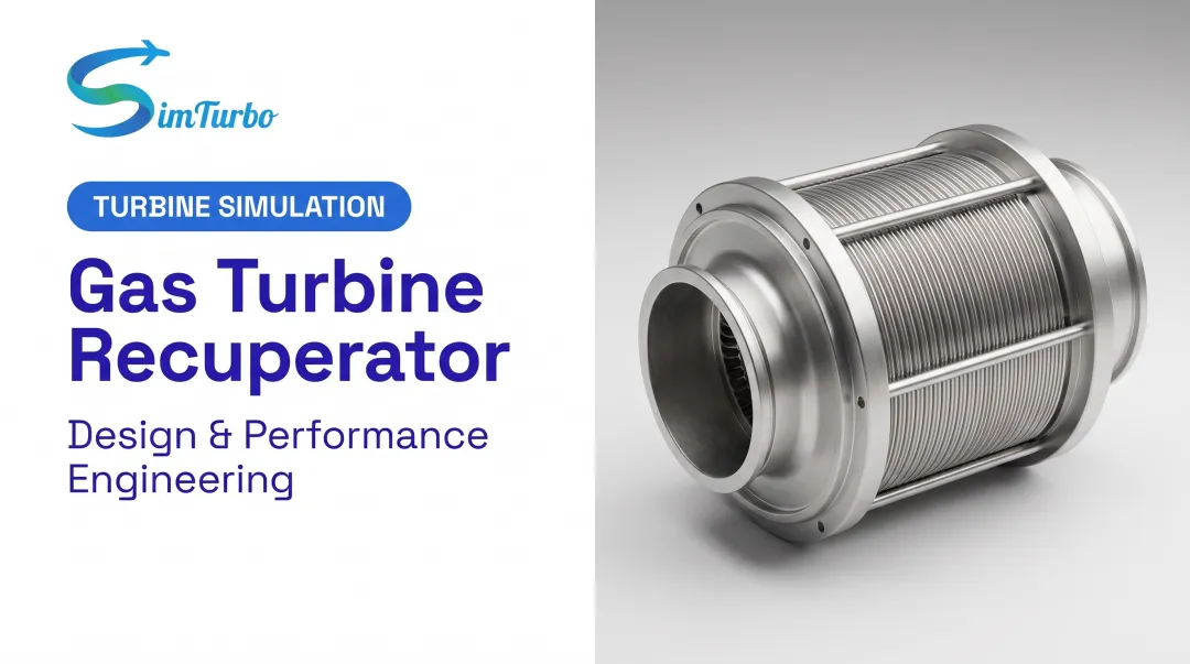
That's where the recuperator comes in. By recovering exhaust heat and using it to preheat combustor inlet air, a well-designed recuperator can claw back much of the efficiency lost to downsizing. This guide covers how these devices work, the design choices engineers face, the trade-offs that come with them, and how simulation tools like SimTurbo let you test ideas before cutting metal.
Key Takeaways
- Recuperators preheat combustor inlet air with exhaust heat, lifting cycle efficiency from ~20% to ~30% at low pressure ratios
- Effectiveness gains add mass, hitting weight-sensitive platforms like UAVs hardest
- High compression ratio engines see little to no benefit from recuperation
- SimTurbo lets engineers test recuperator integration before hardware commitments
What Is a Compact Microturbine Recuperator?
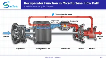
A recuperator is a gas-to-gas heat exchanger. It pulls heat from turbine exhaust and transfers it into compressed air before that air reaches the combustor. Less fuel is needed to reach the required combustion temperature, so overall cycle efficiency rises.
This is a specific function, not a generic label. A recuperator recycles heat within the same thermodynamic cycle, exhaust to inlet air. A general heat exchanger might move heat between two entirely separate fluid loops, such as engine exhaust heating a building's water supply for CHP. Related, but not the same thing.
Why does this matter more at small scale?
- Compact microturbines lose more efficiency to blade tip leakage than larger machines
- Recuperation doesn't fix turbomachinery efficiency, but it recovers energy that would otherwise be wasted out the exhaust
- At pressure ratios of 3–4 and effectiveness above 87%, efficiency rises from roughly 20% to 30% (Shah, CHE2005)
Microturbine generators, sometimes called turbogenerators, combine a compressor, turbine, and generator on one high-speed shaft. The recuperator sits in that flow path, feeding recovered exhaust energy back into the cycle rather than exporting it elsewhere.
Core Design Approaches to Compact Recuperators
Two design philosophies dominate compact recuperator engineering, and each solves a different packaging problem.
Annular and Primary-Surface Designs
Stationary microturbines typically use a donut-shaped, annular core. Capstone's approach folds thin-foil cells (made from HR120 stainless steel) into a counter-flow arrangement wrapped around the turbine-compressor-generator package. This geometry is compact, axisymmetric, and matches thermal expansion characteristics to reduce fatigue cracking (Capstone Energy+, 2023).
A related approach uses cross-corrugated, primary-surface plates rather than tubes. One documented design installed this style in a 100 kWe CHP microturbine, achieving high surface-area density without needing separate tube manifolds.
Microtube Multi-Pass Designs
Aerospace and UAV applications favor a different geometry entirely. A US patent describes a microtube recuperator using more than 10,000 tubes, each under 2 mm inside diameter with wall thickness of just 50-75 micrometers.
Compressed air makes two passes through the exhaust stream via these tubes. Claimed performance includes:
- Effectiveness above 0.8
- Pressure drop under 1.5%
- Total installed mass below 50 lb including ducting (US7775031B2)
These are patent design claims, not independently verified test results, but they illustrate the packaging target aircraft designers chase.
Counter-Flow vs. Cross-Flow
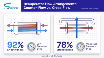
Counter-flow arrangements consistently show up as the higher-effectiveness choice in the literature, since they maximize the temperature differential along the entire flow path. Cross-flow can simplify header design and reduce packaging complexity, but usually trades away some effectiveness. The right answer depends on your NTU, capacity-rate ratio, and pressure-drop budget, not a fixed rule.
The mass cliff is real. NASA's analytical modeling found that raising recuperator effectiveness from 90% to 95% doubles the required heat-transfer area and mass. For a UAV or any weight-constrained platform, that's a brutal trade to make casually (NASA, 2010).
Engineering Trade-Offs Every Designer Must Weigh
Recuperator efficiency isn't free. Four trade-offs deserve attention before committing to a design.
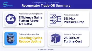
Diminishing returns at high pressure ratios. The thermodynamic benefit of recuperation shrinks as compressor discharge temperature approaches turbine exhaust temperature. The 2005 review places the typical optimum pressure ratio at 3-4, noting that above roughly 8-10, a recuperator adds little value at full load.
Pressure loss can erase the gain. Recuperators introduce pressure drops on both the exhaust and compressor-discharge sides. Design targets in the literature call for total pressure drop below 5%, with about 3% occurring in the core itself. Miss that target and the thermodynamic gain from heat recovery gets offset by lost net output.
Fouling is hard to see coming. Unlike a compressor blade or combustor liner, recuperator channels can't be borescoped. Deposits build up on heat exchange surfaces, reducing heat transfer and increasing pressure drop over time. ORNL's assessment notes that recuperators represent 25%-30% of total microturbine cost, so fouling-related decay is a real economic issue, not just a performance footnote.
Volume works against compactness. An effective recuperator needs physical size to keep pressure drops manageable. That works against the very compactness advantage microturbines are supposed to offer.
For aircraft applications specifically, engineers lean on the Breguet Range Equation to weigh added recuperator mass against fuel savings across a mission profile. One Breguet-based study found that a postulated heat-exchanged aircraft with a 1.25-1.30 engine-weight ratio needed more than 7% specific fuel consumption reduction just to break even on mission fuel burn (Xu et al., ResearchGate).
Mass matters as much as heat transfer.
Where Compact Recuperated Microturbines Are Used
Recuperated cycles show up across a handful of distinct application spaces:
- Distributed power and CHP (roughly 30 kW to 6 MW), where recuperation helps microturbines compete with reciprocating engines—Capstone's C65 reports 28% LHV electrical efficiency and up to 90% total CHP efficiency.
- Heavy-fuel UAV propulsion, where recuperated turboprops offset the fuel-efficiency penalty of small turbines. A 2017 NASC/UAV Turbines proposal scheduled a privately funded TigerShark demo—not a completed government test.
- Defense-funded research, including a 2024 Navy STTR Phase II award ($999,733) for a lightweight VTOL-UAS turbogenerator targeting SFC below 3 lb/hp-hr.
- University lab and capstone programs, where instrumented microturbines give students hands-on exposure to recuperated-cycle losses and real-system behavior.
Several of these examples are funded programs and modeled targets, not verified field results. Distinguishing awards from completed demonstrations matters when you benchmark your own design against "what's been done."
Validating Recuperator Performance Through Simulation
Building and testing a physical recuperator-integrated engine is expensive. Cores need custom tooling, test cells need instrumentation, and a single design iteration can burn weeks. Early-stage simulation is how teams cut that cost before metal is cut. NASA's own propulsion research goals show the scale of the challenge: a full-engine simulation at a single operating point, run within one week, can take roughly 1 million core-hours for a main-gas-path sector—or 10–100 billion for full transient integration (NASA, 2020). Physical testing still isn't going away. It can be reserved for questions models can't yet answer—fouling behavior, manufacturing variation, and thermal-cycle fatigue. Component-based simulation closes that gap. Rather than treating the recuperator as an isolated black box, a platform like SimTurbo models it with the inlet, compressor, combustor, turbine, and shaft in the same flow path. SimTurbo's documented recuperated configuration uses a single-spool turbojet, letting you see how heat recovery ripples through the entire thermodynamic cycle, not just the exhaust duct. Practically, that workflow looks like this:
- Build or modify a single-spool turbojet model with SimTurbo's drag-and-drop components
- Connect a recuperator into the flow path alongside existing components
- Re-parameterize and rerun to compare thermal efficiency and fuel consumption
- Review real-time graphs, cycle diagrams, and P/T behavior across altitude, Mach, and ambient temperature
- Export results to Excel, MATLAB/Simulink, or Python for deeper post-processing
- Repeat before committing to physical hardware SimTurbo's steady-state modeling has been benchmarked against NASA Lewis Research Center J85-GE-21 test data, holding within ±2% for thrust, flow rate, temperature, and specific fuel consumption. That check covers the base turbojet, not a recuperator-specific case, but it backs the solver used for cycle-level recuperator studies. University teams and capstone engineers exploring recuperated cycles can also use discounted classroom and lab licensing.

Frequently Asked Questions
What is the purpose of a recuperator?
A recuperator recovers heat from turbine exhaust and uses it to preheat combustion air. This reduces the fuel needed to reach combustion temperature, raising overall cycle efficiency.
What is the difference between a recuperator and a heat exchanger?
A recuperator is a specific type of heat exchanger that recycles heat within the same engine cycle, from exhaust to inlet air. A general heat exchanger can transfer heat between any two separate fluid streams, including external loops.
What are microturbine generators?
Microturbine generators, or turbogenerators, combine a small gas turbine, compressor, and generator on a single high-speed shaft. Many designs pair them with a recuperator to boost electrical efficiency.
Are recuperators always beneficial for gas turbines?
No. Recuperators lose their thermodynamic advantage at high compression ratios and always add some pressure loss. Above a pressure ratio of roughly 8–10, the benefit at full load becomes negligible.
How does recuperator fouling affect performance over time?
Deposits on heat exchange surfaces reduce heat transfer and increase pressure drop over time. This is harder to catch early than other turbine issues since recuperator channels can't be borescoped.
Can recuperator designs be tested before building physical hardware?
Yes. Platforms like SimTurbo let engineers model recuperator placement within the full engine architecture and test performance trade-offs virtually, cutting costly prototyping cycles.