Introduction
Turbine blades operate in conditions that defy intuition. Modern high-pressure turbine blades endure gas temperatures approaching 2,900°F, hot enough to exceed the melting point of the nickel-based superalloys they're made from.
Centrifugal forces alone create stresses equivalent to suspending a car from a single blade tip. Each startup and shutdown subjects them to brutal thermal cycling.
Yet these slender, twisted airfoils must extract maximum energy from extreme gas flows with near-perfect reliability. They power commercial airliners across the Atlantic, drive naval destroyers, and generate electricity for entire cities.
Turbine blade design ranks among engineering's hardest challenges. It demands mastery of aerodynamics, materials science, thermodynamics, and mechanical engineering.
This guide explores how engineers balance those competing demands across aerospace, marine, and power generation: extracting maximum energy while surviving extreme temperatures, crushing centrifugal loads, and destructive vibration.
Key Takeaways
- Turbine blades must extract maximum energy from hot gas while surviving temperatures hundreds of degrees above material melting points
- Blade loading (how aerodynamic work is distributed along the surface) directly controls efficiency, stress, and durability
- Single-crystal casting and thermal barrier coatings enable operation at temperatures 200-300°F above base material limits
- Multiple cooling technologies work together to protect blades from gas temperatures approaching 3,000°F (1,650°C)
Fundamental Principles of Turbine Blade Design
Aerodynamic Foundations
Turbine blades function as rotating airfoils that extract energy from high-velocity, high-temperature gas through lift generation and pressure differentials. As hot combustion gas strikes the blade's concave pressure surface, it creates higher pressure than on the convex suction surface. This pressure difference produces net aerodynamic loading that drives the rotor, converting thermal and kinetic energy into shaft power.
The relationship between blade angle, gas flow direction, and energy extraction efficiency is critical. Because blade speed varies dramatically from hub to tip (the tip moves much faster at the same rotational speed), designers twist blades along their span to maintain optimal angles of attack. This twist distributes work extraction efficiently across the entire blade height, preventing inefficient flow angles that waste energy or cause separation.
Key aerodynamic losses include:
- Profile losses from boundary-layer friction and blade surface drag
- Secondary flow losses from complex three-dimensional vortices near hub and shroud
- Tip leakage from gas escaping over the blade tip without doing useful work
MIT research found that blade loading strategy alone can create a 15% difference in tip-leakage losses between forward-loaded and aft-loaded turbine blade designs.
The Structural Challenge
Modern high-pressure turbine blades experience centrifugal stresses exceeding 20,000 times gravity, forces so extreme they would tear most materials apart. A single blade must support its own mass under these tensile loads while maintaining precise aerodynamic shape.
This creates an inherent conflict. Aerodynamic efficiency favors thin, carefully contoured profiles that minimize drag and losses. Structural integrity demands thicker sections that resist bending and creep deformation.
NASA research found that in extreme thermal environments, reducing wall thickness from 0.05 to 0.03 inches improved cooling capability more than doubling internal heat-transfer effectiveness. Thinner walls, however, increase stress and reduce foreign-object-damage tolerance.
Engineers resolve this tension through geometry optimization, strategic material placement, and advanced alloys that hold strength at temperatures where most metals fail.
Environmental Extremes
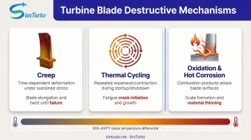
Mitsubishi Heavy Industries' M501J power-generation turbine operates with inlet temperatures reaching 1,600°C, while aerospace engines approach 1,650°C (3,000°F) at maximum power. These temperatures create multiple destructive mechanisms:
- Creep from time-dependent deformation under sustained high-temperature stress, which elongates and twists blades until failure
- Thermal cycling from repeated expansion and contraction during startup and shutdown, which drives fatigue cracks
- Oxidation and hot corrosion from combustion products that attack blade surfaces, forming scale and pits that thin the material
Temperature gradients within a single blade compound these problems. The leading edge might run 300-400°F hotter than the trailing edge, creating internal thermal stresses that add to mechanical loading. Creep-rupture life therefore becomes a principal design constraint. The blade must survive thousands of operating hours without excessive deformation or catastrophic failure.
The Critical Role of Blade Loading
What Is Blade Loading?
Blade loading refers to the aerodynamic force distribution along the blade surface that determines how much work the blade extracts from the gas flow. Think of it as the "pressure signature" that governs energy transfer: regions of high loading extract more energy but create stronger adverse pressure gradients that can cause flow separation.
Engineers distinguish between two critical loading dimensions:
- Spanwise loading: Work distribution from hub to shroud (blade root to tip)
- Streamwise loading: Work distribution from leading edge to trailing edge
Both shape efficiency, mechanical stress, and durability.
Spanwise Work Distribution
Spanwise loading controls how work extraction varies along the blade height, directly affecting secondary flow patterns and efficiency. Common strategies include:
- Free-vortex (constant work): Maintains constant work extraction at all radii, simplifying design but not always optimal
- Constant reaction: Maintains consistent pressure-to-velocity energy conversion ratio from hub to tip
- Optimized distributions: Custom-tailored to reduce hub corner separation and minimize tip losses
Advanced inverse-design methods allow engineers to specify arbitrary spanwise loading distributions that address specific loss mechanisms, such as reducing the hub-corner vortex that wastes energy near the blade root.
Streamwise Loading Strategies
The distribution of work extraction from leading edge to trailing edge creates distinct performance characteristics:
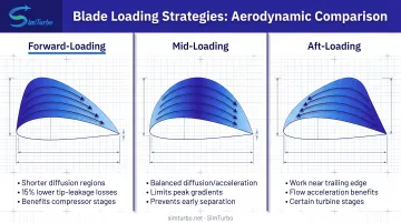
Forward-loading (fore-loading):
- Concentrates work extraction near the leading edge
- Can reduce profile losses through shorter diffusion regions
- Reported tip-leakage losses about 15% lower than comparable aft-loaded designs in published MIT studies
- Often benefits compressor and some turbine stages
Mid-loading:
- Distributes work more evenly along the chord
- Balances diffusion and acceleration regions
- Limits peak local gradients that drive early separation on highly loaded airfoils
Aft-loading:
- Concentrates work extraction toward the trailing edge
- May benefit certain turbine stages where flow acceleration is desirable
Designers control streamwise loading through blade curvature distribution, camber changes, and precise leading/trailing edge geometry.
Design Methods: Direct vs. Inverse Design
Traditional direct design specifies blade angles and geometry first, then analyzes the resulting loading distribution through computational fluid dynamics. This approach requires multiple iterations: guess geometry, analyze performance, adjust, repeat.
Inverse design reverses this workflow: engineers specify the desired loading distribution (targeting optimal pressure gradients and work extraction), then computational methods solve for the blade geometry that produces that loading. You control pressure gradients and work extraction directly, instead of hunting for them through geometry tweaks.
Loading and Mechanical Integrity
Blade loading patterns directly influence structural stress. Aggressive loading gradients (rapid changes in surface pressure) create localized high-stress regions that become crack initiation sites. Areas of peak aerodynamic loading often coincide with maximum mechanical stress, compounding durability challenges.
Loading choices also affect vibration characteristics. Certain distributions raise flutter risk—self-excited vibration driven by coupling between blade motion and unsteady aerodynamic forces—and increase forced-response failure risk from upstream disturbances. Efficient loading only holds if peak stresses and aeroelastic margins stay inside safe limits.
Materials and Manufacturing Innovations
Evolution of Superalloys
Early gas turbines used simple nickel-chromium alloys adequate for modest temperatures. Modern turbine blades employ nickel-based superalloys incorporating cobalt, rhenium, and other elements that enhance temperature capability and creep resistance.
These superalloys derive their properties from a two-phase microstructure:
- Gamma matrix: Ductile face-centered-cubic nickel base that provides toughness
- Gamma-prime precipitates: Coherent, ordered intermetallic particles that resist dislocation motion and maintain strength at temperatures where most metals soften catastrophically
Documented alloy progression:
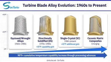
- 1960s-1980s: Wrought and conventionally cast equiaxed alloys
- 1970s-1980s: Directionally solidified (DS) alloys like Rene 80 with columnar grain structure
- 1984-present: Single-crystal (SC) alloys including CMSX family evolved from MAR-M 247
Each generation enabled higher operating temperatures, longer service life, and improved efficiency.
From Polycrystalline to Single Crystal
Conventional casting creates random grain boundaries: interfaces between crystal orientations that become weak points for creep failure at high temperatures. Grain boundaries allow atoms to slide past one another under stress, causing time-dependent deformation.
Directional solidification (DS) technology aligns elongated grains parallel to the primary centrifugal stress direction, eliminating transverse grain boundaries that would fail perpendicular to the load. NASA's 1982 processing study measured 45°F capability improvement from DS processing.
Single-crystal (SC) casting eliminates grain boundaries entirely by growing the entire blade as one continuous crystal. This removes grain-boundary sliding as a failure mechanism and allows compositions with fewer grain-boundary-strengthening additions. NASA documented an additional 45°F operating-temperature increase from single-crystal processing beyond directional solidification, a total 90°F gain through advanced solidification control.
First used in flight engines in 1984, single-crystal turbine blades now dominate high-pressure turbine applications in advanced aerospace engines.
Thermal Barrier Coatings and Surface Treatments
Ceramic thermal barrier coatings (TBCs) provide an insulating layer that reduces blade substrate temperature. The standard system includes:
- Bond coat: Metallic MCrAlY layer (nickel-chromium-aluminum-yttrium) providing oxidation resistance and adhesion
- Ceramic topcoat: Yttria-stabilized zirconia (YSZ) providing thermal insulation
NASA engine testing in 1976 measured coating temperature drops up to 135 K (approximately 243°F) across stabilized-zirconia coatings during cyclic operation. More recent NASA research demonstrated drops of about 450°F across advanced 5-mil coatings at extreme heat flux, under laboratory conditions rather than typical service.
Emerging technologies:
Ceramic matrix composites (CMCs) push temperature capability further. GE Aerospace successfully tested rotating CMC turbine blades through 500 cycles in an F414 engine. Lower CMC density also cuts centrifugal load, which eases mechanical design constraints. Production use is still expanding beyond early engine programs.
Cooling Technologies for Extreme Environments
Why Blade Cooling Is Essential
Modern gas turbines operate with turbine inlet temperatures 500-700°F above the melting point of blade materials. NASA's 1970 cooling study documented gas-path operation near 3,000°F while noting that 2,200°F approached the melting point of nickel-base alloys—making active cooling non-negotiable for performance and survival.
Cooling air bled from the compressor carries an efficiency penalty—cycle models show about 3.7 percentage points under specific conditions—but hotter firing temperatures more than repay that cost through higher cycle performance.
Internal Cooling Strategies
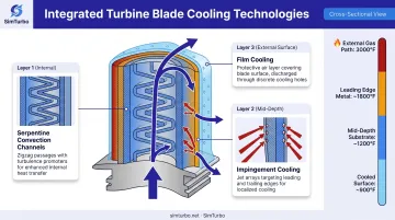
Serpentine convection channels:
- Multi-pass internal passages snake through the blade
- Turbulence promoters (ribs, pins, trips) disrupt boundary layers
- Discrete V-shaped trip strips raise internal heat-transfer coefficients
- Turns generate secondary flows that enhance mixing
Impingement cooling:
- High-velocity jets of cooling air target critical hot spots
- Leading-edge impingement handles the most severe thermal loads
- Trailing-edge impingement protects thin sections
- Jet arrays raise heat transfer where external gas temperatures peak
Integrated flow paths: Cooling air enters through the blade root, flows through serpentine passages with turbulence enhancement, impinges on critical surfaces, then exits through film-cooling holes or trailing-edge slots. Designers size these paths to pull as much heat as possible from the metal before the air is discharged.
External Cooling Techniques
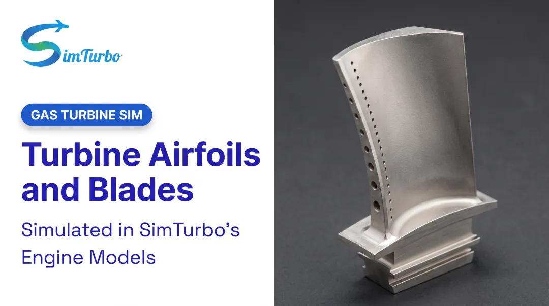
Film cooling injects air through thousands of precisely drilled holes so a thin cooler layer sits between the hot gas and the blade surface, limiting direct exposure to peak combustion temperatures.
Film-cooling effectiveness depends on:
- Hole geometry: Shaped holes with expanding exits reduce jet velocity and momentum, improving attachment at high blowing ratios
- Injection angle: Shallow angles promote attachment; steep angles cause jet lift-off
- Blowing ratio: Balance between cooling flow and mainstream velocity
- Density ratio: Temperature difference between cooling air and mainstream gas
Advanced cooling schemes:
- Shaped diffusion holes: Expanding exit area lowers jet momentum, reducing lift-off and improving lateral coverage
- Leading-edge showerhead: Multiple rows of holes provide intensive cooling where gas temperatures peak
- Trenches: Recessed slots improve film attachment and lateral spreading
- Double-wall cooling: Separate inner and outer shells with cooling air between
Used together, internal convection pre-cools the metal, impingement knocks down local hot spots, and film cooling shields the outer surface. That stack is what lets blades run in gas streams hot enough to melt unprotected alloy.
Design Analysis and Simulation Tools
The Role of Computational Tools
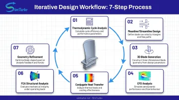
Modern turbine blade design integrates multiple software tools in an iterative workflow:
- Thermodynamic cycle analysis establishes inlet temperature, pressure ratio, and work extraction targets
- Meanline/streamline design solves radial-equilibrium equations for preliminary blade geometry
- 3D blade generation creates detailed airfoil geometry with twist, taper, and cooling features
- CFD analysis validates aerodynamic performance, predicts losses, and identifies hot spots
- Conjugate heat transfer (CHT) couples fluid and solid heat transfer for thermal predictions
- Finite element analysis (FEA) assesses structural integrity, stress concentrations, and life
- Geometry refinement updates the design based on multi-disciplinary results
NASA's streamline design codes solve radial-equilibrium equations for turbine design, while validated CFD tools like GlennHT use benchmark fluid-mechanics and heat-transfer cases to ensure accuracy. With that stack, engineers can explore design variations long before expensive physical testing.
Real-Time Simulation for Design Validation
Physics-based simulation platforms enable engineers to evaluate blade-row performance, off-design behavior, and transient operation before physical prototyping. Real-time simulation helps design teams visualize how blade and component changes affect engine behavior across operating conditions, from startup and acceleration to altitude variation and emergency events.
Tools like SimTurbo provide interactive gas turbine engine simulation with immediate visual feedback through component maps, thermodynamic cycle diagrams, and transient performance graphs. Engineers can modify turbine parameters and observe system-level responses in real time on standard PCs, supporting both design iteration and engineering education programs at universities. Those live parameter changes surface compressor stall, thermal lag, and control-system interactions before anyone commits to hardware.
Integration with Manufacturing and Testing
Design tools must account for manufacturing constraints from the beginning:
- Casting limits: Minimum wall thickness, core support, directional-solidification requirements
- Cooling-hole drilling: Achievable diameter, angle, depth, and positional accuracy
- Inspection access: Line-of-sight for dimensional verification and non-destructive testing
- Coating allowance: Surface preparation and coating-thickness variation
ASME research found that manufacturing-driven blade-shape variation was the main cause of film-hole variation in production blades. Designers have to work from fabrication reality, not ideal geometry alone.
Simulation results also guide instrumentation plans. Cascade rig tests validate isolated blade rows under controlled inlet conditions, while full-engine campaigns place thermocouples and heat-flux gauges on predicted hot spots and high-gradient regions.
Frequently Asked Questions
How are turbine blades designed?
Design starts from cycle targets: inlet temperature, pressure ratio, and work extraction. Engineers set spanwise loading with meanline and radial-equilibrium analysis, choose materials and cooling (often single-crystal nickel superalloys with internal and film cooling), then build 3D geometry and iterate with CFD and FEA until aerodynamic, thermal, and structural limits are met.
What makes single-crystal turbine blades superior to conventional blades?
Single-crystal blades grow as one continuous crystal, so they have no grain boundaries where high-temperature creep failure starts. NASA measured 45°F higher operating temperature capability versus directionally solidified alloys, which extends life in first-stage turbines where gas temperatures approach material limits.
Why do turbine blades have small holes drilled in them?
Those holes supply film cooling: cooler air from inside the blade forms a protective layer on the external surface. That layer shields metal from combustion gases above the melting point, while shaped holes and showerhead patterns balance coverage against the efficiency cost of bleeding compressor air.
What is blade loading and why does it matter?
Blade loading is the pressure distribution along the blade surface that sets work extraction and stress. It drives efficiency (MIT research found 15% leakage-loss differences between strategies), durability under loading gradients, and risk of separation or flutter, so it is a primary aerodynamic design parameter.
How do engineers test turbine blade designs before building engines?
Teams move from CFD and FEA to cascade and spin-rig tests, then instrumented full-engine runs with thermocouples and pressure sensors. NASA's J85-GE-21 work showed agreement within ±2% on thrust, flow, temperature, and fuel consumption, which is why simulation is used heavily before hardware is committed.