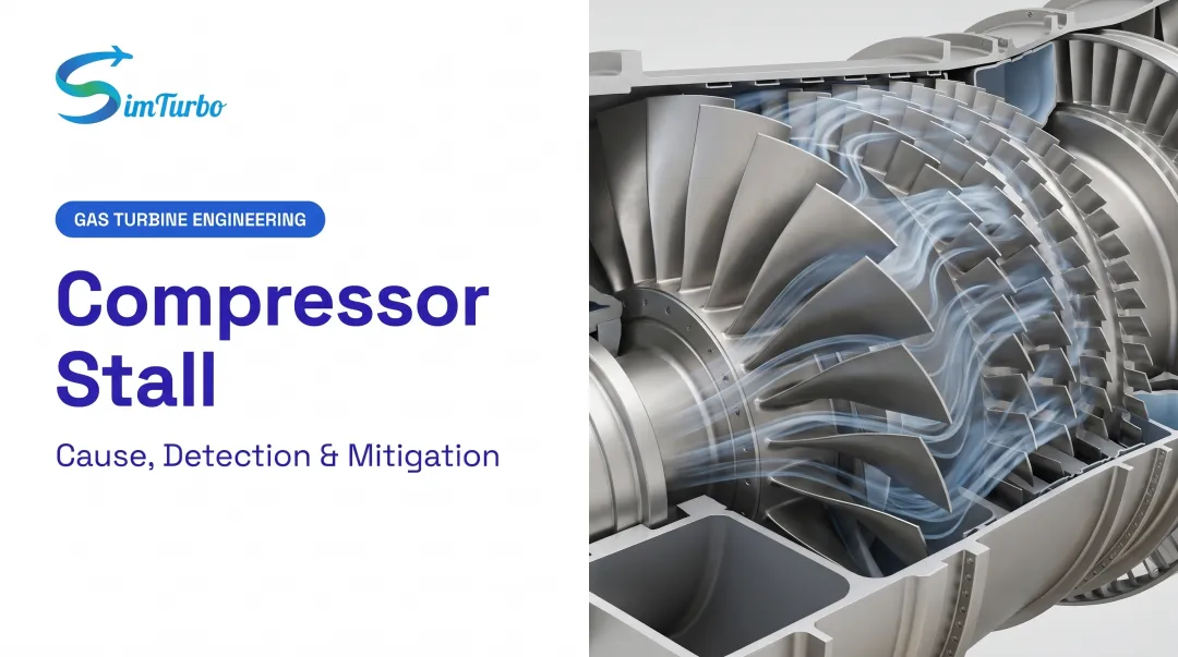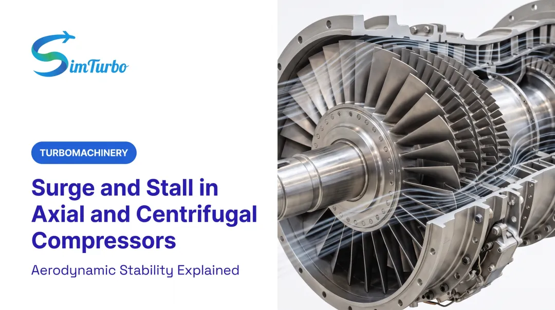
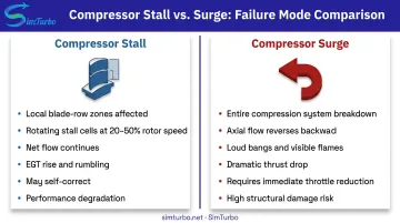
Both compressor stall and surge disrupt airflow and degrade performance, but they are fundamentally different phenomena. Stall involves local flow separation on blade surfaces that may remain contained, while surge is a complete system breakdown with violent flow reversal. Understanding the distinction matters because the operational response, damage potential, and recovery path differ dramatically. According to the FAA, compressor stall occurs when one or more rotor stages fail to pass air smoothly due to a pressure ratio incompatible with engine rpm, while EPRI defines surge as a fluctuation in net compressor flow, not just local circulation disruption.
TL;DR: Key Takeaways
- Rotating stall forms local low-flow cells while average compressor flow continues; surge reverses flow through the whole engine
- Stall can stabilize or self-correct at lower efficiency; surge needs an immediate fuel cut and may cycle destructively
- Controls track surge margin in real time, yet fouling, inlet distortion, and fast transients still shrink that buffer
- Surge brings far higher structural risk: blade breakage, flameout, and possible total engine loss
Compressor Stall vs Surge: Quick Comparison
| Attribute | Stall | Surge |
|---|---|---|
| Scope | Local blade-row or circumferential zones; some passages continue operating | Entire compression system experiences flow breakdown |
| Flow behavior | Rotating stall cells move at 20-50% rotor speed; net average flow remains approximately constant | Axial flow reverses; compressed air is expelled backward through the inlet |
| Observable signs | EGT rise, rpm fluctuation, possible rumbling, vibration increase, minor thrust loss | Loud bangs, visible flames from inlet/exhaust, dramatic thrust drop, high vibration |
| Recovery | May self-correct or stabilize at reduced capacity | Requires immediate throttle reduction; can lock into repeating cycles |
| Severity | Performance degradation, increased blade stress, can progress to surge | High risk of structural damage, blade/vane breakage, catastrophic engine loss |
Why the Difference Matters Operationally
Stall can remain localized. Individual blade passages cyclically stall and recover while adjacent passages continue pumping air. The compressor still delivers compressed air, just less efficiently. If conditions stabilize, the engine may operate indefinitely at reduced output.
Surge is a system-level failure. When the entire compressor can no longer sustain the required pressure rise, flow reverses violently. Previously compressed air rushes backward, disrupting combustion and unloading blades. Once pressure drops, forward flow may resume. If destabilizing conditions persist, the cycle repeats and hammers the structure with each reversal.
What is Compressor Stall?
Compressor stall occurs when airflow separates from the suction side of compressor blade airfoils, creating zones of disrupted flow. Think of it as a wing stall, but occurring inside the compressor's high-pressure-gradient environment.
The Aerodynamic Mechanism
Under normal operation, thin viscous boundary layers allow smooth airflow over blade surfaces. When inlet flow angles increase beyond critical values—or when pressure ratios become too high—boundary layers separate. The blade stops smoothly accelerating the air, and a stalled region forms.
This creates a blockage. Approaching air diverts to adjacent blade passages, increasing their flow angles and causing them to stall in turn. The result is a rotating stall cell—a pocket of low-velocity, recirculated flow that propagates around the compressor annulus.
Rotating Stall Characteristics
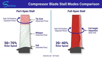
Rotating stall cells move circumferentially, opposite to the direction of rotor rotation. NASA models predict propagation speeds below 50% of rotor speed, with specific cases as low as 27.8% depending on stage count and compressor geometry.
A 2021 AIAA study of a single-stage axial compressor found reversed flow near the rotor tip but continued downstream flow at midspan and hub. Stall cells are spatially complex, not uniform blockages.
Two common modes exist:
- Part-span stall: Separation occurs only at blade tips; cells rotate at 50-70% rotor speed
- Full-span stall: Complete blade-height separation; cells rotate at 20-40% rotor speed, with fewer cells but more severe disruption
Operational Impacts
Rotating stall substantially reduces stage efficiency and pressure-rise capability. Blades experience cyclic structural loading as they repeatedly enter and exit stall cells, accelerating fatigue. If destabilizing factors persist or intensify, rotating stall can propagate through multiple stages, and can escalate into full compressor surge.
FAA-documented symptoms include:
- Exhaust-temperature (EGT) rise
- RPM fluctuation
- Intermittent bangs or rumbling
- Increased vibration
- Noticeable power loss
Common Causes of Compressor Stall
Sudden Backpressure or Flow Disturbances
Downstream events such as combustor blockage, turbine damage, or rapid load changes increase blade inlet angles beyond critical limits. Upstream disturbances such as inlet icing, filter blockage, or crosswind gusts create non-uniform flow that destabilizes blade boundary layers.
Foreign Object Damage and Surface Degradation
Erosion reduces stall margin measurably. A 2019 study of a 12-stage TV3-117VM/VMA axial compressor operating in desert conditions found that erosion reduced pressure ratio, efficiency, and stall margin.
In that case, a 15% stall-margin decrease led to surge, and 6.19 mm of sixth-stage chord wear corresponded to a 15-17% margin reduction. The compressor's serviceability limit was 730-750 flight hours in that harsh environment.
FOD, blade-tip wear, and erosion disrupt boundary-layer behavior, making blades more sensitive to off-design inlet angles. Excessive tip clearances allow more flow to leak over the tips, reducing work input and cutting margin further.
Off-Design Operation
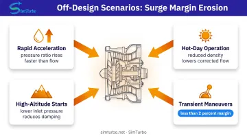
Rapid throttle movements, extreme maneuvers, or operation outside the engine's design envelope push the operating line toward the surge line:
- Rapid acceleration: Fuel flow increases faster than the compressor can respond, raising pressure ratio before airflow catches up.
- Hot-day operation: Reduced air density lowers corrected flow, moving the operating point leftward on the compressor map.
- High-altitude starts: Lower inlet pressure reduces aerodynamic damping, making stall cells easier to trigger.
- Transient maneuvers: A 2012 NASA simulation found that an accelerated throttle schedule reduced high-pressure-compressor surge margin below 2% during a hot-day transient, though it remained above zero.
What is Compressor Surge?
Compressor surge is a complete axial breakdown of compression. The compressor can no longer work against downstream pressure, and compressed air violently reverses direction, expelling backward through the engine inlet.
The Physics of Flow Reversal
When all compressor stages reach their pressure-ratio limits simultaneously, or when rotating stall propagates through the entire compressor in under a second—the compressed air behind the compressor overcomes its pumping capacity. High-pressure air flows backward along the path of least resistance: through the compressor itself.
Surge develops in an instant, not through gradual degradation.
Observable Signs
Surge events are unmistakable:
- Extremely loud bangs as flow reverses and shockwaves form
- Visible flames shooting from inlet and exhaust as combustion disrupts
- Dramatic vibration spikes from sudden aerodynamic unloading and reloading
- Instantaneous thrust loss as forward momentum collapses
Surge Cycle Behavior
Once pressure ratio reduces through flow reversal, the compressor may briefly return to stable airflow. But if the root cause persists (excessive fuel flow, downstream blockage, or degraded hardware), pressure rebuilds and surge repeats. This creates a locked-in surge cycle, hammering the engine with repeated flow reversals until the operator intervenes or components fail.
Severe Damage Risks
A 2013 ASME study documented catastrophic compressor failures during emergency-shutdown sequences in a hybrid fuel-cell/turbine power system at the National Energy Technology Laboratory. Simultaneous fuel and load cutoff triggered compressor surge and stall; previous test runs had experienced complete compressor destruction under similar conditions.
Engineers eventually mitigated the risk by ramping fuel valves nonlinearly during shutdown.
High mechanical loads during surge can:
- Break compressor rotor blades and stator vanes
- Liberate blade fragments that destroy downstream turbine components
- Crack casings and housings
- Damage combustor liners and seals
- Lead to total engine loss if cycles repeat
Why Surge is More Dangerous Than Stall
Stall may stabilize, allowing continued operation at reduced capacity. Surge always represents a complete failure of the compression system and requires immediate corrective action.
While the FAA warns that even continued compressor stall can cause flameout and physical damage, surge is harsher: it drives whole-system pressure and flow cycling that accelerates structural failure.
- Stall cells stay local; surge reverses flow through every stage at once
- Blades unload and reload hundreds of times per minute in locked-in surge cycles
- Each cycle adds mechanical stress and raises the odds of component failure
A 2006 ASME paper links compressor aerodynamic instability under degraded or extreme conditions to high-cycle blade fatigue and possible gas-turbine failure.
Stall vs Surge: Understanding the Progression and Operational Response
Compressor stall often serves as a precursor to surge. Local stall cells can propagate and destabilize the entire compressor if conditions keep eroding surge margin. Left unaddressed, stall can escalate into full-system surge.
Compressor Map Concept
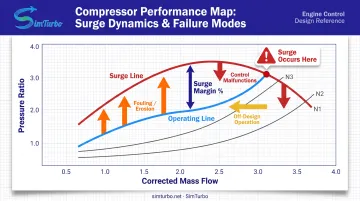
Engineers visualize compressor behavior on a compressor map: a plot of pressure ratio versus corrected mass flow at different rotor speeds. Two critical lines appear:
- Operating line: The path the compressor follows during normal operation as power changes
- Surge line: The boundary beyond which stable compression breaks down
Surge margin is the vertical distance between the operating line and surge line, expressed as a percentage. It represents the safety buffer before surge occurs.
Various factors erode this margin:
- Operating line rises: fouling, dirt buildup, erosion, tip-clearance growth, inlet distortion
- Surge line drops: control malfunctions, excessive fuel flow, downstream blockages
When the two lines meet, surge occurs.
Modern Prevention Through FADEC
Full Authority Digital Engine Control (FADEC) systems monitor dozens of parameters in real time and automatically adjust:
- Variable guide vanes (VGVs): Optimize inlet flow angles across operating conditions
- Compressor bleeds: Relieve pressure during startup and acceleration
- Fuel flow: Prevent excessive pressure-ratio buildup during transients
- Exhaust-nozzle area: Manage backpressure in afterburning engines
A 2006 GE study found that sensor-based tests provided about 30-40 milliseconds (roughly four rotor revolutions) of reaction time before stall. Modern control logic uses that narrow window to modulate fuel, open bleeds, and adjust vanes to keep the operating point safely away from the surge line.
Operator Response Differences
For stall:
- Reduce throttle smoothly while monitoring for recovery
- Watch EGT, rpm, and vibration trends
- Avoid abrupt inputs that could destabilize further
- If stall stabilizes, continue reduced-power operation until maintenance assessment
For surge:
- Immediate, steady throttle reduction to lower pressure ratio
- Assess whether surge is self-recovering or locked-in
- Follow engine-specific Quick Reference Handbook (QRH) procedures strictly
- Do not attempt to restore full power until root cause is identified and corrected
- Expect mandatory inspection and possible component replacement
Real-World Examples and Prevention Best Practices
Power-Generation Case: Emergency-Shutdown Surge
A 2013 ASME study of a hybrid fuel-cell/turbine system at NETL recorded surge during emergency shutdown. Uncoordinated fuel and load-bank cutoff had already destroyed compressors in earlier tests. Later controlled runs showed stall and surge right after shutdown activation.
Case highlights:
- Trigger: Uncoordinated fuel and electrical-load changes during emergency stop
- Warning signs: Rapid pressure-ratio collapse as fuel was cut while turbine load remained
- Impact: Compressor destruction in early tests; surge and stall confirmed in controlled experiments
- Corrective action: Nonlinear fuel-valve ramp-down improved shutdown stability when the load bank was offline
Factors That Erode Surge Margin in Combined-Cycle Plants
These plant conditions push the operating line toward the surge line:
- Inlet air filter fouling: Higher pressure drop, lower corrected flow, operating line shifts left toward surge
- Hot-day operation: Lower air density cuts mass flow and damping; NASA's 2012 study showed margin below 2% in hot-day acceleration
- Rapid load changes: Grid-following duty needs fast throttle response and spends margin during transients
- Water or steam injection: NOx-control injection changes mass flow and temperature profiles, so compressor matching shifts. A 2006 ASME study found inlet cooling alone rarely causes instability, but it can tip a unit that already has thin margin
Prevention Best Practices
- Inspect and replace inlet filters on schedule. Track differential pressure and change filters at manufacturer limits. EPRI recommends high-efficiency filtration to limit particulate ingestion.
- Run online and offline compressor washes. Demineralized-water online washes slow capacity loss between outages. A 2014 ASME test found most offline cleaning in the first five minutes at ~0.2% liquid-to-air ratio, recovering about 30% of fouling-related power loss.
- Monitor tip clearances. Larger gaps cut efficiency and surge margin. Use periodic borescope checks and fix wear early. A 2023 ASME study found circumferential casing grooves cut tip-gap mass flow by about 16% near stall.
- Warm up the engine properly. Ramp temperature and speed gradually so thermal growth stabilizes and clearance swings stay small.
- Train operators on early cues. Teach unusual vibration, EGT swings, RPM hunting, and engine-specific QRH steps. Rehearsing shutdowns and compressor-matching limits in a gas-turbine simulator (such as SimTurbo) builds that recognition before a live event.
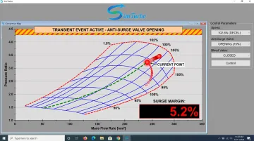
SimTurbo's Real-Time Simulation for Training
SimTurbo's gas turbine simulation platform allows operators and engineering students to visualize compressor operating conditions in real time without risking actual equipment. Its compressor-map interface overlays the operating line and surge line, showing how the operating point moves during transient events.
In a documented example, SimTurbo displayed surge margin at 20-25% during normal operation, falling below 5% during an afterburner transient. Users watched adaptive control logic modulate fuel flow and nozzle area to restore margin, observing the cause-and-effect relationship between control actions and stability.
Training Scenarios
- Startup and slam-acceleration sequences
- Throttle bursts, load changes, and deceleration
- Compressor stall and surge events
- Sensor-failure scenarios and FADEC response
- Afterburner engagement with rapid back-pressure rise
The dashboard updates temperature-entropy (T-S) diagrams, compressor maps, and performance graphs as conditions change. Users learn to recognize how fouling, tip-clearance growth, inlet distortion, and rapid transients erode surge margin.
Transient data exports to CSV or Excel for post-analysis, supporting classroom labs, capstone projects, and operator familiarization programs.
SimTurbo offers discounted pricing for universities, classrooms, and research labs, plus a 30-day free trial. Contact (779) 390-4786 or info@simturbo.net for academic program details.
Frequently Asked Questions
What causes a surge in a compressor?
Surge occurs when the operating pressure ratio meets or exceeds the surge-line limit. Common triggers include downstream blockages, excessive fuel flow, inlet distortion, fouling, control faults, and fast transients that erase remaining margin. Flow then reverses violently against the backpressure.
What happens when a compressor stalls?
Stall creates rotating pockets of separated airflow that cut efficiency and raise blade loading. You may see EGT rise, rpm swings, rumble, vibration, and power loss. Mild stall can self-clear; severe stall can progress into full surge.
What is stalling, surging, and choking in a compressor?
Stalling is local airfoil separation that forms rotating disturbances while mean flow stays roughly steady. Surging is a system-wide instability with fluctuating net flow, often including violent reversal. Choking is the high-flow limit when velocity goes sonic at a throat, not a low-flow instability.