Introduction: What Are Gas Turbine Engine Compressors?
Gas turbine engine compressors raise ambient air to high pressure before combustion. That compression step anchors the thermodynamic cycle behind aircraft, ships, and power plants.
Pushing air from low to high pressure is like forcing water uphill. Blade rows manage boundary layers and adverse pressure gradients so the flow keeps moving downstream instead of separating.
Efficiency matters because the compressor consumes a large share of turbine power just to drive that work. When the design misses the mark, stall and surge can wipe out stability and performance gains.
Modern engines use two dominant compressor types:
- Axial-flow — multistage machines that reach pressure ratios above 40:1
- Centrifugal-flow — simpler stages that deliver about 4:1 compression each
This article covers compressor fundamentals, how they operate, performance behavior, stall and surge, and uses in aerospace, marine, and power generation.
Key Takeaways: Essential Facts About Gas Turbine Compressors
- Axial compressors drive large commercial and military engines at pressure ratios from 15:1 to over 40:1
- Centrifugal compressors fit helicopters, APUs, and regional turboprops at about 4:1 per stage with fewer parts
- Stall and surge are aerodynamic instabilities that can damage hardware if operating margins collapse
- Compressor maps and matching decisions shape performance in aerospace, marine, and power-generation engines
How Gas Turbine Compressors Work: The Fundamentals
The compressor occupies the inlet section of the gas turbine cycle, drawing in ambient air and compressing it to high pressure and density before delivering it to the combustor for fuel mixing and ignition. Unlike turbines, which operate in favorable pressure gradients as gases expand, compressors face an adverse pressure gradient: they must force air from low to high pressure against natural resistance.
Boundary layers on compressor blades sit at the center of that challenge. These thin viscous regions transition from zero velocity at the blade surface to freestream velocity. Under the adverse pressure gradient inherent in compression, they separate easily when blade angles get too steep or back-pressure rises too fast.
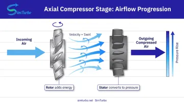
Rotor and stator blade functions:
- Rotor blades spin with the shaft, adding kinetic energy that raises airflow velocity and pressure
- Stator blades stay fixed, remove rotor-imparted swirl, and convert kinetic energy into static pressure rise
- Interstage alignment from each stator straightens flow into the next rotor so multi-stage compression stays efficient
As air progresses through the compressor, its pressure and density increase. To hold axial velocity roughly constant, blade height decreases stage by stage. High-pressure stages therefore use shorter blades, where tip-clearance tolerances are critical to performance and efficiency.
Types of Gas Turbine Compressors
Three primary compressor architectures serve the gas turbine industry: axial-flow, centrifugal-flow, and mixed-flow. Each offers distinct flow paths, geometries, and performance characteristics suited to specific engine sizes and applications.
Axial-Flow Compressors
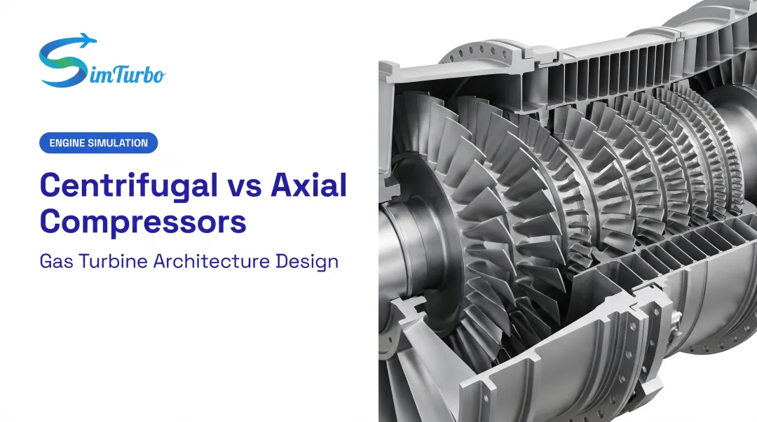
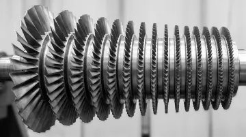
Axial compressors move air parallel to the engine's axis of rotation through multiple stages of rotor and stator blade rows. Modern industrial gas turbines demonstrate the range of stage counts: the Siemens SGT-800 employs 15 stages to achieve 21.1:1 to 22.0:1 compression, while GE 7F variants use 14 or 18 stages depending on model.
The GE LM6000 aeroderivative engine illustrates multispool architecture with a 5-stage low-pressure compressor plus 14-stage high-pressure compressor, delivering overall pressure ratios from 30.7:1 to 34.8:1.
In commercial aviation, the LEAP-1A (Airbus A320neo) achieves 40:1 and the LEAP-1B (Boeing 737 MAX) reaches 41:1 overall engine pressure ratio. These figures represent total engine compression, not individual compressor-section values.
Axial compressors dominate large aircraft engines and utility-scale industrial turbines because they deliver component efficiencies exceeding 90% and maintain compact frontal areas that minimize aerodynamic drag.

Centrifugal-Flow Compressors
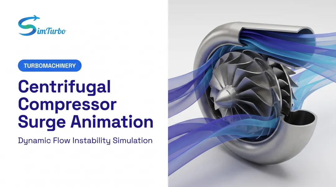
Centrifugal compressors draw air axially into a rotating impeller, then accelerate it radially outward through centrifugal force. A diffuser then converts that kinetic energy to pressure.
NASA research on a rotorcraft centrifugal stage measured 4.68:1 pressure ratio with 85.5% polytropic efficiency at design flow and speed, demonstrating the performance achievable in single-stage designs.
A 2020 AIAA high-pressure-ratio core compressor study specified a final centrifugal stage delivering 4.0–5.0:1 compression. While single stages achieve these ratios, multistage centrifugal designs face mechanical complexity because flow must be ducted back to the engine centerline between stages.
Current applications include:
- APS2300 APU (Pratt & Whitney): single-stage centrifugal compressor
- PW200 helicopter engine (Pratt & Whitney): single-stage centrifugal compressor
- PT6A turboprop (Pratt & Whitney): multistage axial plus single-stage centrifugal compressor
Centrifugal designs excel in applications where simplicity, ruggedness, and compact axial length outweigh frontal size and efficiency trade-offs.
Mixed-Flow Compressors
Mixed-flow (diagonal) compressors represent a hybrid design where airflow travels at an angle between purely axial and purely radial paths. A 2007 study of the Pratt & Whitney PW210 compressor (derived from the PW600 family) documented one mixed-flow stage plus one centrifugal stage.
This architecture offers a compromise between axial efficiency and centrifugal compactness, particularly for small turbofan engines where large centrifugal diffusers would create excessive frontal drag.
Axial vs. Centrifugal: Performance and Design Comparison
| Dimension | Axial-Flow | Centrifugal-Flow |
|---|---|---|
| Pressure ratio per stage | NASA transonic research stage: 1.842:1 (varies by loading) | ~4:1 to 4.68:1 single stage |
| Multistaging | 14–19 stages common in industrial/aero engines | Difficult; requires complex ducting between stages |
| Efficiency | >90% component efficiency in large engines | 85.5% polytropic efficiency (NASA research stage) |
| Frontal area | Narrow, favorable for aircraft installation | Wider, adds aerodynamic drag |
| Mechanical complexity | Many blade rows; often requires variable geometry | Fewer parts; typically no variable geometry |
| Typical applications | Commercial jets, military fighters, utility turbines | Helicopters, APUs, small turboprops, regional aircraft |
Selection criteria:
- Axial: Maximum pressure ratio and efficiency—best for large commercial turbofans, industrial power turbines, and military jet engines
- Centrifugal: Simplicity, ruggedness, and rapid spool-up—best for smaller engines, APUs, and auxiliary power
Operational Challenges: Compressor Stall and Surge
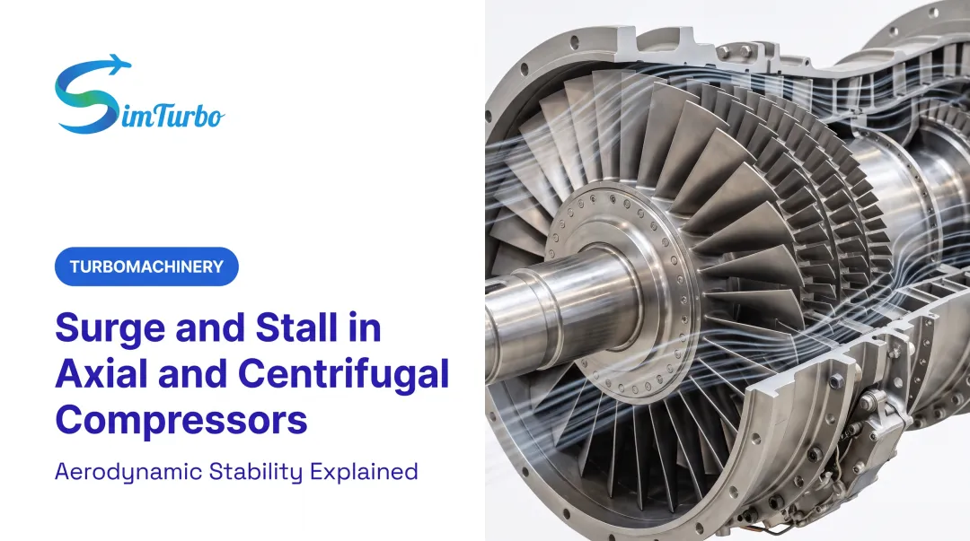
Compressor stall occurs when airflow separates from compressor blades due to excessive inlet angles or adverse pressure gradients. This localized flow breakdown causes loss of lift, pressure rise, and efficiency. In some cases, stall cells form and propagate around the compressor annulus.
NASA measured a one-cell rotating stall pattern at 50.6% shaft speed in a 2006 low-speed compressor rig, while a 2021 AIAA study reported 37% rotor speed in a different axial compressor. Propagation speed varies with compressor design.
Compressor surge is a more severe instability involving rapid, violent flow reversal throughout the entire compressor. Surge produces pulsating or oscillating flow that can expel flames from the inlet and exhaust, accompanied by loud banging noises and potential structural damage.
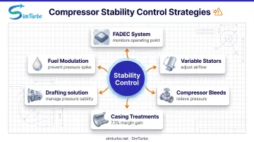
Modern prevention strategies include:
- Full-Authority Digital Engine Control (FADEC) systems that continuously monitor compressor operating points relative to stall/surge lines
- Variable-pitch stators that adjust blade angles to maintain proper flow conditions
- Compressor bleeds that relieve excess back-pressure during transient maneuvers
- Casing treatments such as grooved or slotted housings; one ASME study measured a 7.3% stall-margin increase with grooved casing treatment
- Rapid fuel modulation to prevent excessive pressure rise
Stall can develop in milliseconds, while mechanical actuators need far longer to respond. That gap puts a premium on predictive control algorithms and conservative operating margins.
Applications Across Aerospace, Marine, and Power Generation
Aerospace Applications
Commercial aviation relies on multistage axial high-pressure compressors. The LEAP-1A and LEAP-1B turbofans powering the Airbus A320 family and Boeing 737 MAX achieve 40:1 and 41:1 overall engine pressure ratios, respectively, enabling high thermal efficiency and fuel economy for single-aisle operations.
Military jet fighters employ advanced axial designs for high thrust-to-weight ratios. The GE F414, powering the F/A-18E/F Super Hornet, delivers 30:1 pressure ratio with 170 lb/s airflow and 22,000-lb thrust class. The Pratt & Whitney F119 features a six-stage compressor in a counterrotating core architecture for the F-22 Raptor.
Helicopters and regional turboprops favor centrifugal or hybrid architectures. The PW200 helicopter engine uses a single-stage centrifugal compressor, while the PT6A turboprop combines multistage axial compression with a final centrifugal stage, balancing performance with simplicity and reliability for general aviation.
Those same compressor tradeoffs scale into stationary power, where stage count and pressure ratio track plant duty rather than thrust-to-weight.
Industrial Power Generation
Large frame gas turbines employ 14–18 stage axial compressors for base-load and combined-cycle power plants. The Siemens SGT-800 uses a 15-stage compressor delivering 21.1:1 to 22.0:1 compression, while GE 7F variants feature 14-stage (7F.05) or 18-stage (7F.04) compressors for 50 Hz and 60 Hz grid applications.
Aeroderivative units adapted from aircraft engines bring 30–40:1 compression to distributed and peaking power applications. The GE LM6000, derived from the CF6 turbofan, combines a 5-stage low-pressure compressor with a 14-stage high-pressure compressor for overall ratios from 30.7:1 to 34.8:1, offering rapid start capability and high efficiency in smaller footprints.
Aeroderivative cores also move to sea, where power density and fuel burn dominate ship design.
Marine Propulsion
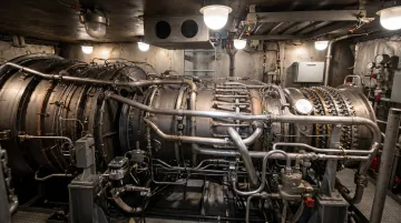
Aeroderivative gas turbines power naval vessels and high-speed ferries. The GE LM2500 marine engine employs a 16-stage compressor, using aircraft-derived technology for high power density and fuel efficiency in destroyer and frigate propulsion.
Engineering Design Tools
Across aerospace, power, and marine programs, engineers need to model compressor behavior before hardware is cut. SimTurbo, from Controls Research LLC, uses a component-based architecture to compare compressor types, pressure ratios, and operating conditions without treating the engine as a black box.
Key capabilities include:
- Drag-and-drop virtual prototyping and performance optimization
- Control-law validation with built-in control components
- J85-GE-21 single-spool turbojet results checked against NASA Lewis Research Center test data within ±2% for thrust, flow rate, temperature, and TSFC
The platform also runs transient cases such as startup, slam acceleration, and surge. Engineers can overlay compressor maps with thermodynamic cycles, track operating lines against surge lines, and watch margins fall from 20–25% in normal operation to below 5% in rapid transients, so control systems can be validated before hardware testing.
Frequently Asked Questions
What are the two main types of compressors used in gas turbine engines?
Axial-flow compressors move air parallel to the shaft through multiple blade stages and dominate large engines, while centrifugal-flow compressors accelerate air radially outward through a spinning impeller and suit smaller applications requiring simplicity and ruggedness.
How does a gas turbine engine compressor work?
The compressor draws in ambient air and raises its pressure and density as rotating rotor blades add kinetic energy and stationary stator blades convert that velocity into pressure. The result is high-pressure air ready for fuel mixing and combustion.
What is the difference between axial and centrifugal compressors?
Axial compressors add a modest pressure rise per stage but stack stages easily for high overall ratios. Centrifugal compressors deliver about 4:1 per stage, yet multistaging is mechanically harder, so they fit smaller, simpler engines.
What causes compressor stall and surge in gas turbines?
Stall occurs when airflow separates from compressor blades due to excessive inlet angles or adverse pressure gradients. Surge is a more severe instability where the entire compressor experiences flow reversal, often triggered by downstream blockages, rapid throttle changes, or operating too close to the stability limit.
Why do modern aircraft engines use axial compressors instead of centrifugal?
Axial compressors reach higher overall pressure ratios (20–40:1) through easy multistaging, run above 90% component efficiency, and present a smaller frontal area that cuts aircraft drag. That mix suits high-performance commercial and military engines despite greater mechanical complexity.
What is a multistage compressor and why is it important?
A multistage compressor links stages in series so pressure ratios multiply—for example, about 1.4:1 per stage across 15 stages yields roughly 20:1 overall. That stacking is how modern engines reach the 15–40:1 ratios needed for strong thermal efficiency.