When a rotor fails, the consequences aren't small. Unplanned outages, safety incidents, and lost efficiency all trace back to rotor problems more often than any other single component. EPRI calls the rotor the most critical and expensive major component in a gas turbine fleet, and that's not an exaggeration.
This article covers how rotors are designed, what materials engineers choose and why, the damage mechanisms that shorten rotor life, and how simulation tools like SimTurbo let engineers and students study rotor behavior before committing to expensive hardware changes.
Key Takeaways
- Rotors integrate compressor, shaft, and turbine sections into one rotating assembly
- Choose materials (nickel superalloys, steel, titanium) based on temperature, stress, and corrosion exposure
- Watch for thermal fatigue, creep, erosion, and corrosion as the primary damage mechanisms
- Simulation platforms let engineers model rotor-connected components in real time, cutting reliance on physical prototypes
- Upgrades demand a full-system review, not just a rotor-level analysis
What Is a Gas Turbine Rotor?
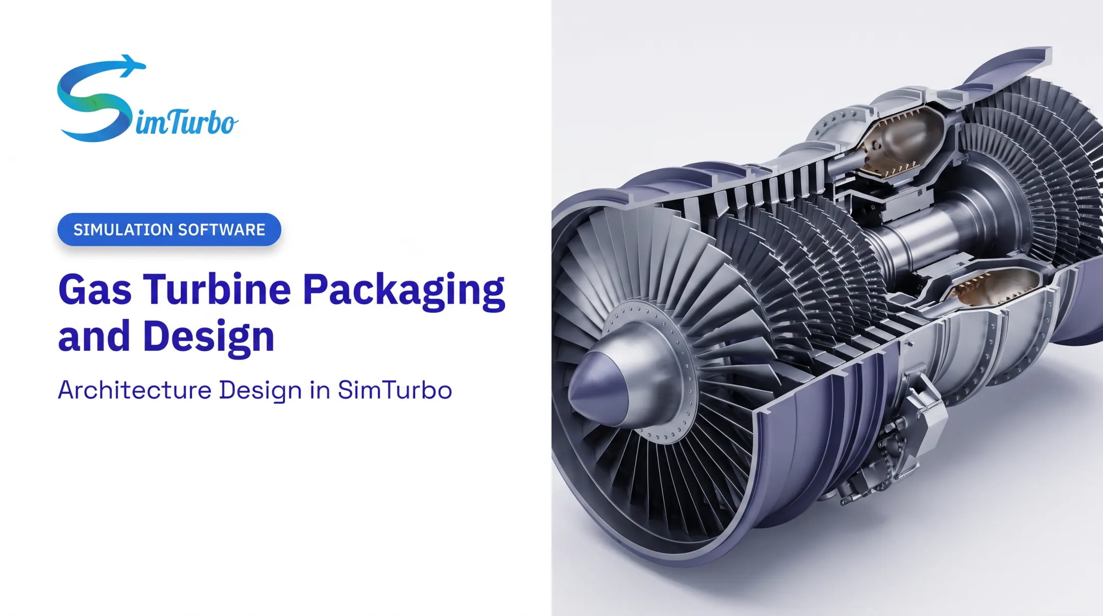
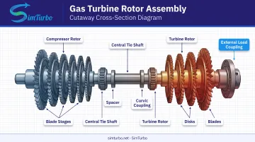
A gas turbine rotor is the complete rotating load path: compressor disks and blades, one or more shafts, turbine disks and blades, and the hardware that ties it all together: tie bolts, spacers, and curvic couplings. A documented Westinghouse design from the 1950s stacked disks on a torque tube with long through-bolts, using curvic couplings to transmit torque while tolerating thermal distortion. That basic architecture, in more advanced form, still shows up in modern industrial rotors.
Rotor vs. stator is straightforward: the rotor spins; the stator directs airflow around it. Everything that rotates as one connected mass belongs to the rotor.
Operating conditions are extreme. Combustion gas temperatures can reach up to 2,600°F (roughly 1,427°C) at the turbine inlet, according to the Department of Energy.
That's gas-path temperature, not metal temperature. Cooled blades and disks run cooler and unevenly across their surface, but the thermal load is still severe. Rotational speeds vary by design: a NASA educational turbojet model uses a design point of 16,540 RPM, though heavy industrial rotors, gas-generator spools, and free power turbines each spin at different rates depending on their job.
Despite these extremes, manufacturing tolerances on rotor components are held to fractions of a millimeter. The rotor connects to its load, whether a generator or a propulsor, through couplings and shafts that must stay precisely aligned even as the whole assembly heats, cools, and flexes.
Key Components of a Rotor Assembly
- Compressor rotor — compresses incoming air through a series of rotating blade stages
- Turbine rotor — extracts energy from expanding combustion gases to drive the compressor and the load
- Central/tie shaft — connects compressor and turbine sections, transmitting torque
- Blades — do the aerodynamic work of compressing or extracting energy from the gas
- Spacers and curvic couplings — maintain disk spacing and transmit torque across joints while tolerating thermal growth
- Couplings — link the rotor to the external load, such as a generator
Rotor Design, Materials, and Types
Rotor design is a balancing act between aerodynamic efficiency, structural durability, and the realities of manufacturing. Engineers lean on computational fluid dynamics (CFD) and finite element analysis (FEA) to model airflow and stress before a single part gets forged.
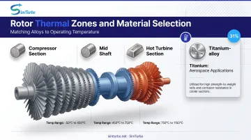
Material selection tracks thermal duty. A 1958 ASME paper on the Westinghouse W-121 already showed the pattern: alloy-steel compressor disks on an alloy-steel shaft, Inconel turbine blades, and Discalloy (25% nickel, 13% chromium) in the hottest early turbine disks. That thermal zoning still drives material choices today:
- Nickel-based superalloys: Hot-section wheels and spacers under peak temperature and stress (EPRI cites IN706 in current industrial rotors)
- Alloy steels: Compressor disks and shafts, where temperatures stay lower
- Titanium: Aerospace parts that need high strength-to-weight; NASA dual-alloy impellers pair creep-resistant airfoils with fatigue-resistant hubs
Architecture Varies by Application
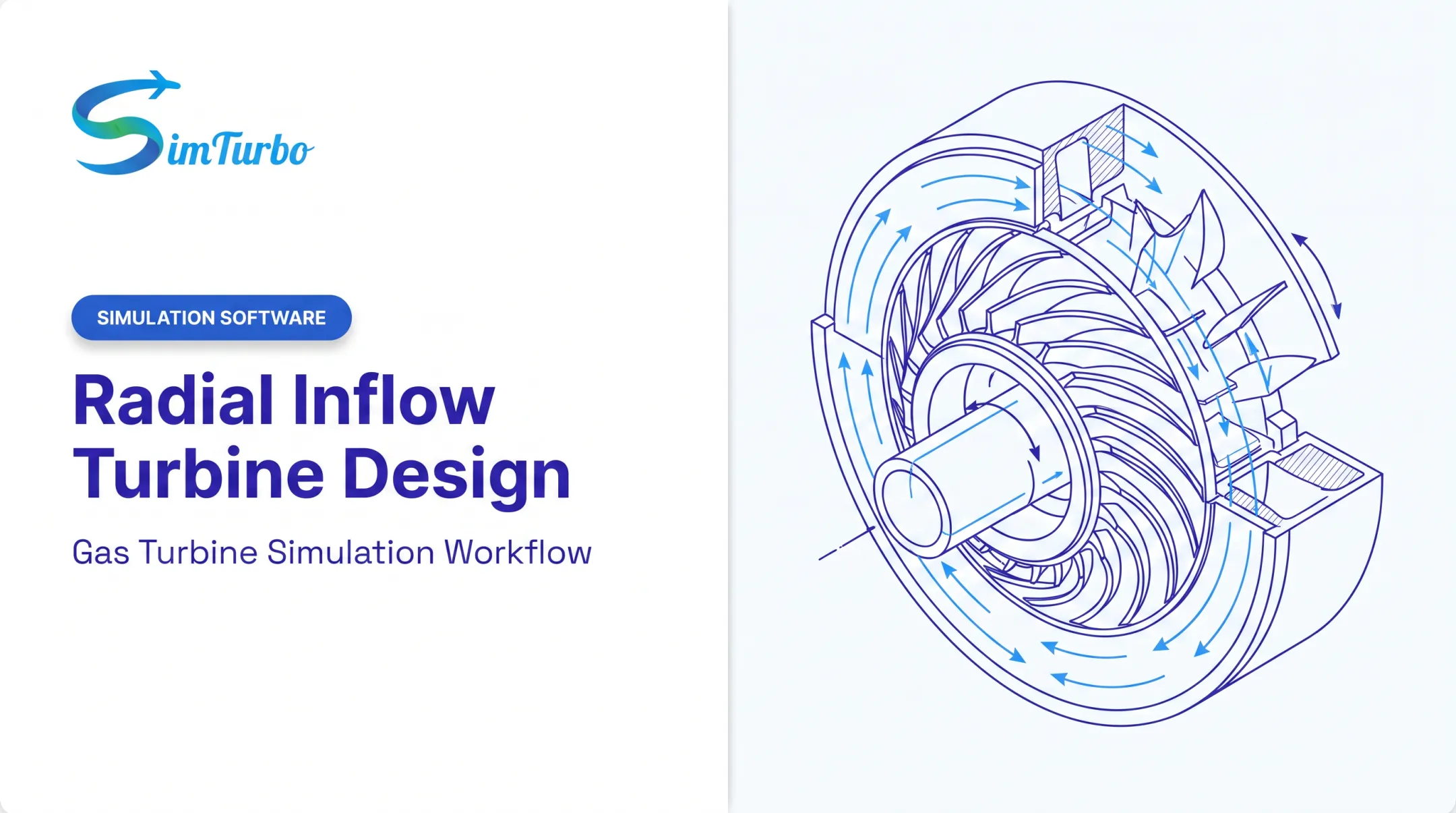
Axial compressors dominate large turbojets, turbofans, and heavy industrial units because they handle high mass flow with strong pressure ratios. Centrifugal (radial) compressors show up more in smaller, compact turbines where space matters more than flow volume. Mixed-flow designs exist, but they're a niche solution, not a mainstream architecture.
Whatever the architecture, the hardware path is similar: forging sets the base disk shapes, precision machining holds tight tolerances, and non-destructive testing (NDT) catches subsurface flaws before the rotor ever spins.
Duty cycle still governs how long that hardware stays in service. EPRI reports that many F-class industrial rotors hit an OEM assessment threshold around 144,000 fired hours or 5,000 starts. That figure is a trigger for evaluation, not a guaranteed failure point. Actual life depends on temperature history, start-stop cycles, and inspection findings.
Why Rotor Balancing Matters
Even a small mass imbalance creates centrifugal force that grows with the square of rotational speed. An ASME case study on the LM2500 marine gas turbine found gas-generator rotor unbalance was the root cause of high vibration; trim balancing brought vibration back to acceptable levels. ISO 21940-11 and ISO 21940-12 set procedures and tolerances for rigid and flexible rotors. Classify the rotor first, then apply the matching tolerance calculations.
Common Rotor Damage Mechanisms and Maintenance Practices
Rotor damage rarely comes from a single cause. It's usually a combination working together over thousands of operating hours.
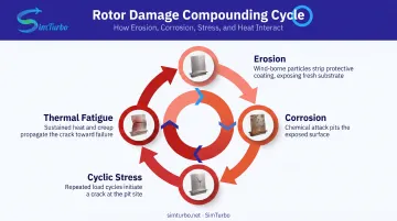
Thermal fatigue and creep. Repeated startup and shutdown cycles create thermal strain at bores, bolt holes, and blade attachments: classic crack-initiation sites. Creep adds a second layer: sustained high temperature plus centrifugal stress causes slow, time-dependent deformation, and it interacts with fatigue rather than acting alone.
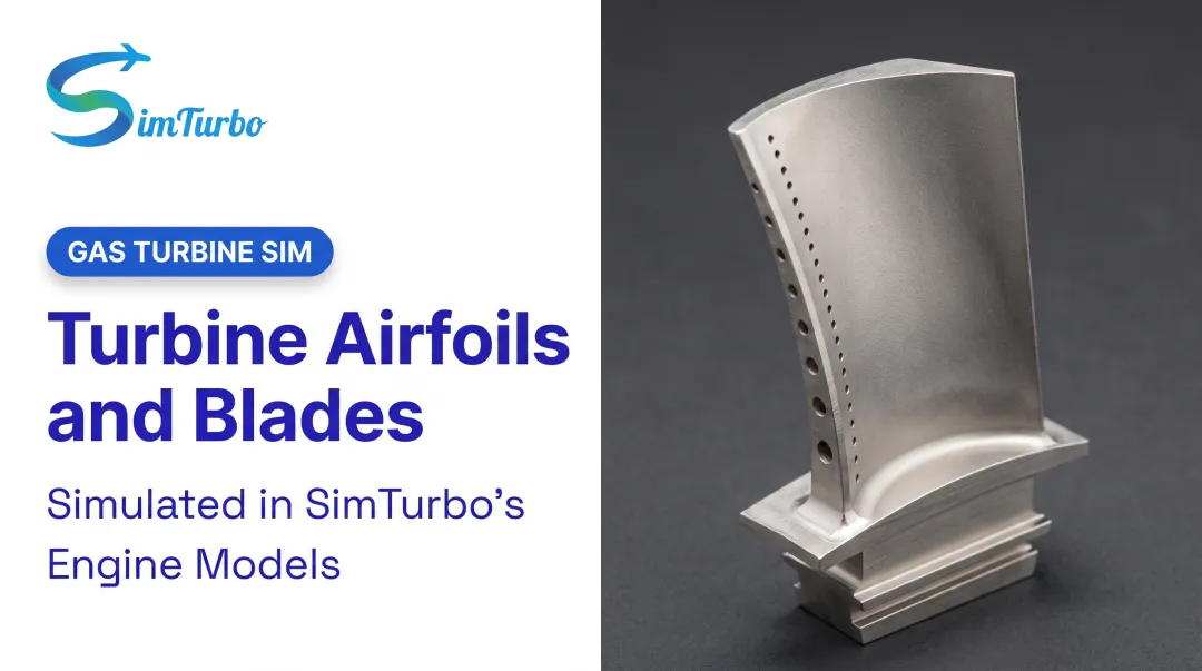
Erosion and foreign object damage (FOD). Sand, ash, and airborne particulates wear down blade surfaces and coatings over time. NASA's erosion research on thermal-barrier-coated turbine blades combined physical testing with predictive modeling to understand this wear pattern. Larger ingested objects cause more immediate damage — dents and notches that become fatigue-crack starting points.
Corrosion and oxidation. Sulfur, sodium, and chloride exposure accelerate oxidation and hot corrosion, particularly as disk temperatures climb toward 700°C in some nickel-based components.
These mechanisms compound: erosion exposes fresh substrate, corrosion pits the surface, and cyclic stress propagates a crack from the pit. That's why inspection needs to account for actual defect geometry and temperature history, not treat each mechanism as independent.
Diagnostic tools that catch problems early:
- Vibration analysis to flag imbalance or bearing issues
- Borescope inspection for visual confirmation of blade and disk condition
- Non-destructive testing (NDT) for subsurface cracks and defects
Maintenance practices that limit damage growth:
- Log starts, trips, and hot-section hours against OEM life limits
- Align borescope and NDT intervals with real temperature and cycle history
- Repair or retire parts once crack size or creep strain exceeds allowables
How Simulation Software Supports Rotor Design, Analysis, and Validation
Physical rotor testing is expensive and slow. Every prototype cycle costs time, materials, and instrumentation. That's driving a shift toward digital simulation earlier in the design process, not as a replacement for physical testing but as a way to focus it.
Component-based simulation platforms let engineers model compressors, shafts, and turbines together, rather than treating the whole engine as an opaque black box.
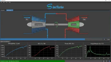
SimTurbo, built by Controls Research LLC, is a Windows-based platform built for this approach. Its architecture lets users connect shafts, compressors, and turbines interactively, along with inlets, combustors, and nozzles, to represent a full flow path in real time.
For rotor-adjacent work specifically, SimTurbo supports:
- Transient simulation of startup, shutdown, throttle changes, acceleration, and load changes
- Shaft and spool modeling across single-spool and dual-spool turbojet configurations
- Real-time monitoring of RPM, EGT, thrust, and surge margin, with live graphs during a simulation run
- Data export to CSV or Excel for post-processing RPM, temperature, and fuel-consumption trends
SimTurbo doesn't offer a dedicated structural rotor-dynamics solver for critical speeds, torsional modes, or bearing whirl. What it does provide is a way to study spool-speed behavior, control response, and thermodynamic performance without a physical test rig.
That is exactly where university and capstone teams get the most value. Students can build engine models from components, run transient scenarios like compressor stall or sensor failure, and watch the results unfold on a standard PC.
Confidence in any simulation depends on validation against real data. SimTurbo's model was benchmarked against NASA Lewis Research Center test data for the J85-GE-21 single-spool turbojet, matching thrust, flow rate, temperature, and thrust-specific fuel consumption within ±2%. That accuracy gives engineers a basis for trusting predicted performance before they commit to hardware changes.
Evaluating Rotor Replacement and Upgrade Decisions
Swapping in a rotor upgrade to squeeze out more output or efficiency sounds straightforward. It rarely is.
A rotor is one node in a larger system. Push more power through it, and downstream equipment—generators, pumps, emissions control systems—may not have the margin to handle the change.
A rotor upgrade that isn't matched to the rest of the train can create a new bottleneck somewhere else in the plant.
Emissions compliance is a separate, easy-to-miss trap. Under 40 CFR 52.21, a physical or operational change only counts as a major modification when it produces both a significant emissions increase and a significant net emissions increase, based on a two-step project-and-netting analysis.
Pollutant significance thresholds vary: 40 tons/year for NOx and SO2, 100 tons/year for CO, and lower thresholds for particulate matter. Output change alone isn't the legal test; the emissions math is.
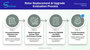
Before committing to a rotor replacement or uprate:
- Document baseline utilization and emissions for the current configuration
- Model the projected performance change across the full system, not just the rotor
- Screen for PSD/NSR and NSPS applicability given the scope of the modification
- Consult the state or local permitting authority early, since most permits run through EPA-approved state programs
This is where broader engineering evaluation justifies the investment. Controls Research LLC's consulting work covers thermodynamic analysis, feasibility studies, and performance diagnostics that fit this kind of system-level review. The goal is to evaluate the whole engine and its connected equipment, not the rotor in isolation.
Frequently Asked Questions
What is a rotor in a gas turbine?
A gas turbine rotor is the complete rotating assembly, including compressor and turbine wheels connected by a shaft, that converts combustion energy into mechanical power. It spins the load, whether a generator or a propulsor, through connected couplings.
How long does a gas turbine rotor typically last?
Life varies by design and duty cycle, but many F-class industrial rotors approach OEM assessment thresholds around 144,000 fired hours or 5,000 starts. Maintenance quality, start-stop frequency, and inspection history all extend or shorten that window.
What causes gas turbine rotor damage?
The main mechanisms are thermal fatigue from repeated heating and cooling, high-temperature creep, erosion from particulates, and corrosion from sulfur, sodium, or chloride exposure. These often compound rather than acting alone.
What materials are gas turbine rotors made from?
Turbine sections typically use nickel-based superalloys for high-temperature strength, compressor sections use alloy steels, and titanium appears in weight-sensitive aerospace applications. The choice depends on the section's temperature and stress profile.
How is a gas turbine rotor different from a compressor or turbine section alone?
The rotor is the full rotating assembly: compressor, shaft, and turbine sections locked together. A compressor or turbine section alone is only one piece of that system, not the complete rotor.
Can simulation software help design or troubleshoot gas turbine rotors?
Yes. Platforms like SimTurbo let engineers model rotor-connected shafts, compressors, and turbines and validate performance before hardware testing. SimTurbo matched NASA test data within ±2% for thrust, flow rate, temperature, and fuel consumption.