This comparison matters specifically for gas turbine systems because centrifugal compressors dominate in aviation and small-to-medium turbines, while reciprocating compressors serve auxiliary and industrial compression roles. Choosing the right technology impacts engine efficiency, weight, and maintenance requirements—making it a critical decision for engineers designing turbojets, turboshafts, and power generation turbines.
This article focuses on compressors in gas turbine engine contexts, not general industrial compression, with relevance for engineers, students, and designers working with modern turbine systems.
TL;DR
- Centrifugal compressors fit gas turbine engines: high speed, compact design, continuous flow
- Reciprocating compressors suit high-pressure, low-flow auxiliary systems, not engine cores
- They differ in flow type, pressure ratio per stage, efficiency curves, and cycle integration
- Use centrifugal/axial in-engine; reciprocating for auxiliaries and stationary power
Centrifugal vs Reciprocating: Quick Comparison
Side-by-side, these are the differences that usually drive compressor selection in gas turbine and industrial work.
| Dimension | Centrifugal Compressor | Reciprocating Compressor |
|---|---|---|
| Flow Characteristics | Continuous, steady flow from a rotating impeller; smooth delivery that fits combustor and turbine cores | Pulsating piston-cylinder flow; discontinuous delivery poorly suited to continuous-flow turbine cores |
| Pressure Ratio per Stage | About 4:1 to 5:1 per stage; multi-staging needed for higher overall ratios in aerospace and power turbines | About 3:1 to 5:1 per stage; multi-stage setups with intercooling can reach much higher ratios |
| Efficiency Profile | Peak polytropic efficiency 78–85% near design point; falls off near surge or choke | Fairly steady 75–80% across a wide pressure-ratio band; less sensitive to operating-point shifts |
| Typical Applications | Aircraft engines (turboshafts, APUs, small turbojets), marine and industrial gas turbines (5–50 MW), turbochargers | Engine-start ground support, auxiliary pneumatics, stationary industrial compression, fuel-gas boosting, high-pressure storage |
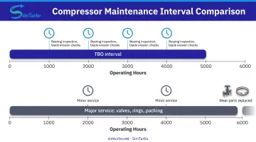
| Maintenance & Durability | Fewer moving parts; 5,000+ hour TBOs common in aerospace; main risks are blade erosion, bearing wear, and surge | More wear parts (valves, rings, packing); annual to three-year intervals; higher vibration and reciprocating loads |
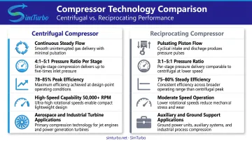
What is a Centrifugal Compressor?
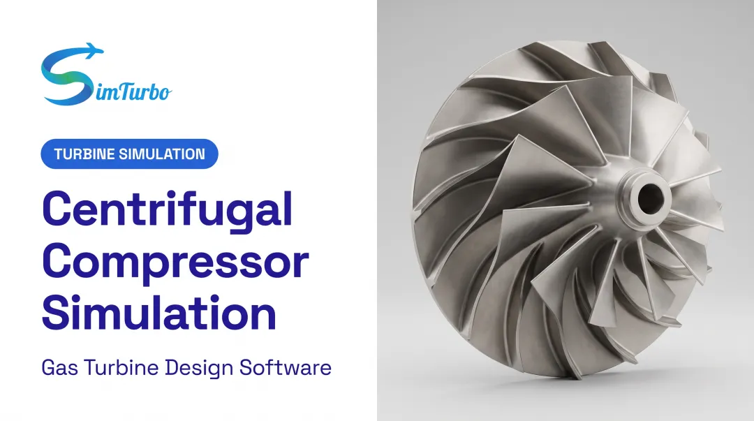
Centrifugal compressors are dynamic machines that accelerate gas radially outward through an impeller, then convert that kinetic energy into pressure through diffusion. NASA defines them by radial flow turning and flags pressure ratio, shaft speed, and efficiency as the main performance variables.
Continuous flow and direct shaft coupling make them a natural fit for high-speed gas turbine integration.
Operating Principles and Performance Boundaries
Gas enters axially at the impeller eye. Rotating blades accelerate it radially outward, then the diffuser converts that velocity into pressure through controlled deceleration.
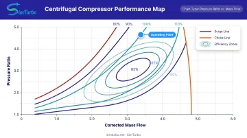
Compressor maps define the operating envelope. They plot corrected mass flow against pressure ratio and show:
- Constant-speed lines for different rotational velocities
- Efficiency islands where performance peaks
- Surge line (left boundary) where flow becomes unstable
- Choke line (right boundary) at maximum flow capacity
Engineers must keep operating points inside these limits. A NASA rotorcraft study measured a final centrifugal stage at 4.68 pressure ratio, 85.5% polytropic efficiency, and 7.5% stall margin at 21,789 rpm. That data sketches a realistic aerospace performance envelope.
Why Centrifugal Compressors Dominate Gas Turbine Engines
Gas turbine engines favor centrifugal compressors for clear technical reasons:
- Handle 50,000+ rpm and match turbine shaft speeds without gearing (EASA-certified Arriel 2 turboshaft: 39,095–39,158 rpm at 100% N2)
- Pack high pressure ratio into a short axial length, which helps aerospace weight and volume limits
- Deliver steady flow that supports combustor flame stability and turbine inlet conditions better than pulsating positive-displacement machines
- Reach about 4:1 to 5:1 in a single modern stage, with stacked stages when higher overall compression is required
Efficiency Characteristics and Off-Design Operation
Peak polytropic efficiency typically lands in the 78–85% range near the design point (intended speed and mass flow). Off-design operation is less forgiving: efficiency falls as the machine approaches surge at low flow or choke at high flow.
NASA's HECC study showed predicted peak efficiency dropping from about 87.3% at 85–90% corrected speed to 85.8% at 105%. That speed sensitivity is why aerodynamic matching to the turbine, plus active control, matters across the operating range.
When a single stage cannot hit the overall pressure ratio, designers stack centrifugal stages for power-generation and propulsion duty—and the matching problem grows with each added stage.
Integration with Turbine Systems
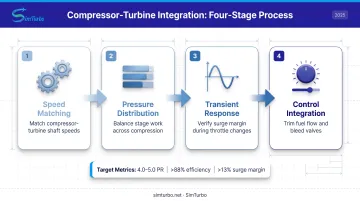
Centrifugal compressors only work well in an engine when they are aerodynamically matched to the turbine. Designers focus on:
- Compressor–turbine speed relationships so both machines run efficiently on the same shaft
- Pressure-ratio distribution that balances stage work and avoids local surge or choke
- Transient response that keeps the unit clear of surge during throttle or load changes
Engine controls track surge margin and trim fuel flow, variable geometry, or bleed valves to stay stable. Turboshaft final-stage design targets often call for a 4.0–5.0 stage pressure ratio, >88% polytropic efficiency, and >13% surge margin. Meeting those numbers in practice usually means iterating compressor maps, turbine capacity, and control logic in simulation before hardware is committed.
Use Cases of Centrifugal Compressors
Small-to-Medium Gas Turbine Engines
Centrifugal compressors are widely used in turboshaft engines for helicopters and marine propulsion, where compact size and high speed are critical. Safran's Arrano 1A turboshaft for the Airbus H160 uses a two-stage centrifugal compressor in the 1,100-1,300 shp engine class.
In auxiliary power units (APUs), centrifugal stages provide reliable compression in extremely compact packages. Pratt & Whitney's APS2300 APU uses a single-stage centrifugal compressor to meet aircraft electrical and pneumatic demands.
Industrial Gas Turbines for Power Generation
Centrifugal compressors appear in smaller frame gas turbines (5-50 MW range) for distributed power, combined heat and power (CHP), and mechanical drive applications in oil and gas facilities.
Kawasaki's M1A-13 features a two-stage centrifugal compressor delivering 1,510 kW output, while the M1A-17D produces 1.81 MWe at 28.1% electrical efficiency for small industrial CHP installations.
These applications benefit from several practical strengths:
- Stable performance across varying ambient conditions
- Moderate maintenance requirements
- Simpler control systems than larger axial-compressor turbines
Turbochargers and Superchargers
Centrifugal compressors are the standard in automotive and marine turbocharging, compressing intake air to increase engine power density.
The same architecture also appears in hybrid-electric aviation research. Electric motors can drive centrifugal compressors independently of engine speed, which supports more flexible power management and better efficiency across flight profiles.
What is a Reciprocating Compressor?
Reciprocating compressors are positive displacement machines using pistons driven by a crankshaft to compress gas within cylinders. They differ from dynamic (centrifugal/axial) compressors used in turbine engines because they create discrete compression events rather than continuous flow.
Operating Principles and Cycle Mechanics
Gas is drawn into a cylinder during the intake stroke when the suction valve opens. The piston then compresses the gas, and at the appropriate pressure the discharge valve opens to release it (Ariel compressor theory). This cycle repeats continuously, with valves cycling up to 1,800 times per minute in high-speed designs (Ariel valve data).
The result is inherently pulsating flow, requiring discharge piping to include pulsation dampeners and surge bottles to smooth output. Multi-staging with intercooling is common for high-pressure applications, reducing gas temperature between stages to improve efficiency and approach isothermal compression.
Operational Characteristics
Reciprocating compressors achieve very high single-stage pressure ratios—typically 3:1 to 5:1, and one documented industrial example reached an overall ratio of 8.84 with a per-stage ratio of 2.97 (Ariel case study). They handle wide pressure ratio variations and maintain relatively constant efficiency across operating conditions, unlike centrifugals, which are sensitive to speed and flow changes.
However, reciprocating compressors have lower maximum flow capacity for a given footprint, higher vibration due to reciprocating mass, and more complex maintenance requirements involving valves, rings, packing, and lubrication systems.
Why Reciprocating Compressors Are Not Used Inside Gas Turbine Engines
Reciprocating compressors cannot serve as core compression stages in gas turbines for these reasons:
| Requirement | Gas Turbine Core | Reciprocating Compressor |
|---|---|---|
| Flow process | Open Brayton-cycle compression with continuous mass flow | Cylinder suction, compression, and discharge events creating pulsating delivery |
| Motion | Radial acceleration by rotating blades | Cyclic check-valve and piston system with sliding/wearing parts |
| Speed capability | Demonstrated speeds of 21,789 rpm (HECC) and 39,095-39,158 rpm (Arriel N2) | Moderate-speed, low-piston-speed equipment designed for API 618 process applications |
| Integration | Continuous flow into combustor for stable flame | Pulsating delivery conflicts with combustor stability and turbine flow requirements |
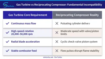
Pulsating delivery, speed limits, valve inertia, and sliding-part wear make them a poor fit inside high-speed, continuous-flow turbine cores.
Where Reciprocating Compressors Appear in Gas Turbine Contexts
While not used inside engines, reciprocating compressors serve important auxiliary roles:
- Ground support equipment — providing high-pressure starting air for large turbofan and turboshaft engines in military and commercial aviation operations
- Auxiliary air systems — supplying pneumatic controls and instrument air for gas turbine power plants
- Fuel-gas boosting — compressing fuel gas to turbine combustors, often with lower power draw during load changes (Power Engineering)
Use Cases of Reciprocating Compressors
Ground Support and Starting Systems
Reciprocating compressors provide high-pressure starting air for large turbofan and turboshaft engines in military and commercial aviation ground operations. One jet-engine air start unit delivers 400 PPM at up to 40 psig for continuous-flow starting.
Starting systems must deliver enough mass flow and pressure to spin turbine rotors to self-sustaining speed. Continuous-flow air carts often operate near 40 psig, while stored-air or bottle-start systems typically need 200–450 psi, depending on engine size and ambient conditions.
Industrial Auxiliary Compression
Reciprocating compressors serve refineries, chemical plants, and power plants in roles such as:
- Instrument air
- Process gas compression
- Refrigeration
- Fuel-gas boosting beside power turbines
Ariel identifies lubricated and non-lubricated fuel-gas boosters among reciprocating applications. These sit beside gas turbine cores as auxiliary equipment, not in the core gas path.
In fuel-gas boosting, reciprocating units can consume less power than centrifugals during turbine load changes. Trade-offs include nonlinear step control, more wearing parts, lower reliability, and roughly annual maintenance.
High-Pressure Niche Applications
Reciprocating compressors excel in applications requiring extreme pressure ratios—up to 5,000+ psi in hypercompressor designs—for gas storage, pipeline injection, or specialty chemical processes. Those levels sit well above typical gas turbine envelopes, which rarely exceed 500 psi even in advanced aero-engine cores.
Where pressure matters more than flow rate, reciprocating machines are often the practical choice for:
- CNG fueling stations
- High-pressure gas storage
- Specialized industrial processes
Centrifugal vs Reciprocating: What is Better?
Decision Factors Specific to Gas Turbine Applications
If the need is for in-engine compression, centrifugal (or axial) is the only viable choice due to continuous flow and high-speed compatibility. No reciprocating compressor can match the 20,000-50,000+ rpm speeds or smooth flow required by combustor and turbine systems.
If the need is for auxiliary systems or ground support, evaluate based on:
- Pressure requirements: reciprocating compressors handle higher pressures (500-5,000+ psi) more efficiently than centrifugals in low-flow scenarios
- Flow capacity: centrifugals deliver higher volume flow rates in a given footprint
- Duty cycle: intermittent or batch operation favors reciprocating; continuous 24/7 operation favors centrifugal
- Control characteristics: reciprocating units use step unloading; centrifugals use speed or variable geometry
Situational Recommendations
Choose centrifugal compressors when:
- Gas turbine work in aerospace, marine, or power generation where shaft speed, weight, and aerodynamic integration matter
- Application requires continuous smooth flow above 10,000 rpm shaft speeds
- Compact, lightweight packaging is essential
- Maintenance intervals must be maximized (thousands of operating hours)
Choose reciprocating compressors when:
- Auxiliary systems require high pressure ratios with low flow (starting air, CNG fueling)
- Duty is intermittent or variable with long idle periods
- Pressure exceeds 500 psi and flow is modest
- Wide turndown ratio (ability to operate efficiently at part load) is needed
- Cost per unit pressure ratio is the primary economic driver
Efficiency and Lifecycle Considerations
Centrifugal compressors offer lower maintenance with fewer wearing parts and longer service intervals. The Safran Arriel 2D turboshaft engine TBO is 5,000 hours, reflecting whole-engine reliability that includes centrifugal compression stages. They still need careful aerodynamic design and control to avoid surge, especially in transient operation.
Reciprocating compressors provide predictable performance across wide operating ranges and are less sensitive to off-design conditions. They demand more frequent valve, ring, and packing work—process designs often target about 3 years between major service, while fuel-booster applications may need roughly annual maintenance.
The Role of Simulation and Design Validation
Modern gas turbine development relies on performance simulation tools to model compressor behavior, validate operating maps, and predict transient response. NASA's HECC validation used more than 400 steady 3D RANS runs plus time-accurate CFD. Measured results still missed predictions by 2.4 points on efficiency and 4.5 points on stall margin.
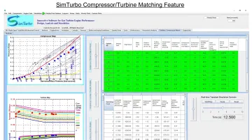
That gap is why engineers still pair map-level models with test data before locking hardware. Tools such as SimTurbo let you exercise compressor matching, control limiters, and off-design transients on a standard PC so centrifugal-stage choices get pressure-tested before the rig.
Real-World Case Study: NASA HECC Rotorcraft Centrifugal Stage Validation
Application and Design Challenge
NASA's High Efficiency Centrifugal Compressor (HECC) program developed the final centrifugal stage of an aero-engine rotorcraft compressor. The engineering team faced multiple challenges:
- Reduced diffuser radius requiring strong impeller-diffuser interaction management
- High exit Mach numbers in a compact geometry
- Close rotor-stator spacing amplifying aerodynamic coupling effects
- Target performance requirements of 4.0-5.0 pressure ratio and ≥88% polytropic efficiency with >13% surge margin
These constraints are typical of modern aerospace turboshaft design, where weight and volume limits force aggressive aerodynamic loading without giving up stability margin.
Simulation Approach and Design Tools
The team employed advanced CFD to explore the design space before hardware testing. More than 400 steady 3D RANS computations plus time-accurate CFD were executed to optimize the 30-degree backswept impeller, splitter vanes, diffuser, and exit guide vanes.
This extensive simulation campaign allowed engineers to:
- Model compressor performance maps across corrected speed ranges
- Predict transient behavior during throttle changes and off-design operation
- Validate control strategies to maintain surge margin during acceleration
- Identify geometry modifications before manufacturing test hardware
Virtual prototyping of this kind catches map, surge, and control issues before metal is cut, which shortens development loops and reduces expensive test-cell surprises.
Measured Outcomes and Lessons Learned
The final hardware achieved 4.68 pressure ratio, 85.5% polytropic efficiency, and 7.5% stall margin at 21,789 rpm design speed. While the pressure ratio met targets, efficiency and stall margin missed pretest predictions by 2.4 and 4.5 percentage points respectively.
This outcome highlights several realities of centrifugal compressor design:
- Even with hundreds of CFD runs, prediction accuracy remains challenging for highly loaded stages
- Surge margin can fall short of targets, requiring control system adaptation or geometry revisions
- Real-world manufacturing tolerances, surface roughness, and assembly effects influence performance
- Simulation tools must be validated against test data to calibrate predictions for future designs
NASA subsequently built a follow-on facility with a vaneless diffuser to isolate impeller performance, additively manufactured transition ducts to study inlet-flow effects, and active clearance control with fast-response instrumentation. That follow-on work underscores how iterative compressor development really is.
HECC also shows why stage CFD alone is not enough for engine teams: you still need cycle-level maps, surge-margin tracking, and throttle-transient checks before hardware. SimTurbo helps engineers and students build virtual engine architectures, place compressor operating points on maps, and exercise control strategies in a controlled environment ahead of test.
See compressor modeling and transient simulation options at simturbo.net.
Conclusion
For gas turbine engine applications, centrifugal compressors are the standard for in-engine compression. High-speed capability, continuous flow, and a compact package make them the practical fit inside the core. Reciprocating compressors still matter in auxiliary and ground support systems, but they are not suitable for integration within turbine engine cores.
Design decisions hinge on flow behavior, efficiency shape, and operating limits. Centrifugals excel in continuous-flow, high-speed environments where aerodynamic integration with combustors and turbines is essential. Reciprocating units deliver high pressure for intermittent auxiliary duty where pulsating flow and lower speeds are acceptable.
Compressor selection and performance modeling determine how well a turboshaft, industrial gas turbine, or academic cycle study holds up in real operation. Platforms such as SimTurbo let engineers iterate quickly, validate compressor maps, and explore transient behavior before hardware commits—useful across aerospace, marine, and power-generation work.
Frequently Asked Questions
What are the key differences between centrifugal and reciprocating compressors?
Centrifugal compressors are dynamic machines that accelerate gas radially for continuous high-speed flow in gas turbines. Reciprocating compressors use pistons for high-pressure intermittent duty. The main differences are continuous vs. pulsating flow, speed capability, and typical applications.
What is the most efficient type of compressor?
It depends on the application. Centrifugal units reach 78–85% polytropic efficiency near design point but fall off-design, while reciprocating units hold roughly 75–80% across pressure ratios. In gas turbines, centrifugals usually win thanks to continuous flow and cycle integration.
Why are centrifugal compressors preferred in gas turbine engines?
They match turbine shaft speeds (up to 50,000+ rpm), deliver smooth continuous airflow, and fit compact, lightweight packages. Staging reaches target pressure ratios, which suits aircraft, marine, and small-to-medium power turbines.
Can reciprocating compressors be used in aircraft engines?
They are not used in gas turbine cores because of pulsating flow, speed limits, and mechanical complexity. They do appear in ground support equipment for starting air and historically powered piston aircraft engines on Otto or Diesel cycles.
How does compressor choice affect gas turbine efficiency?
Higher compressor efficiency means less fuel energy wasted as heat, which raises overall thermal efficiency. Impeller geometry, diffuser design, stage count, and operating point relative to surge and choke all determine whether you hit fuel-economy targets.
What role does simulation play in compressor design validation?
Simulation tools model performance maps, predict transients, and validate stability before hardware is built. Platforms like SimTurbo let engineers and students visualize compressor operation in real time and catch issues virtually instead of in costly test cells.