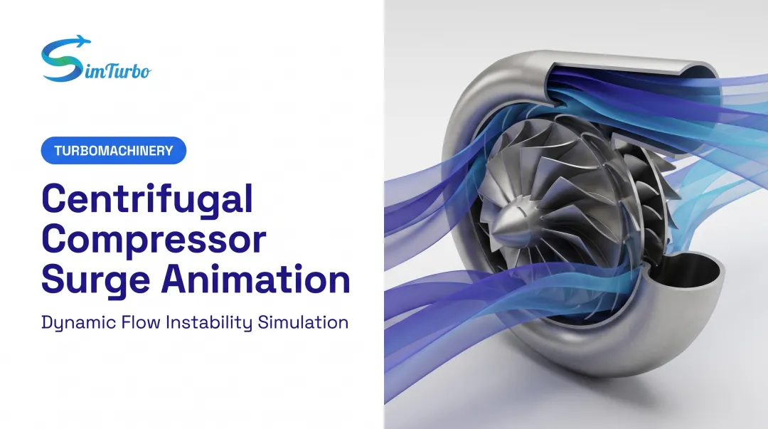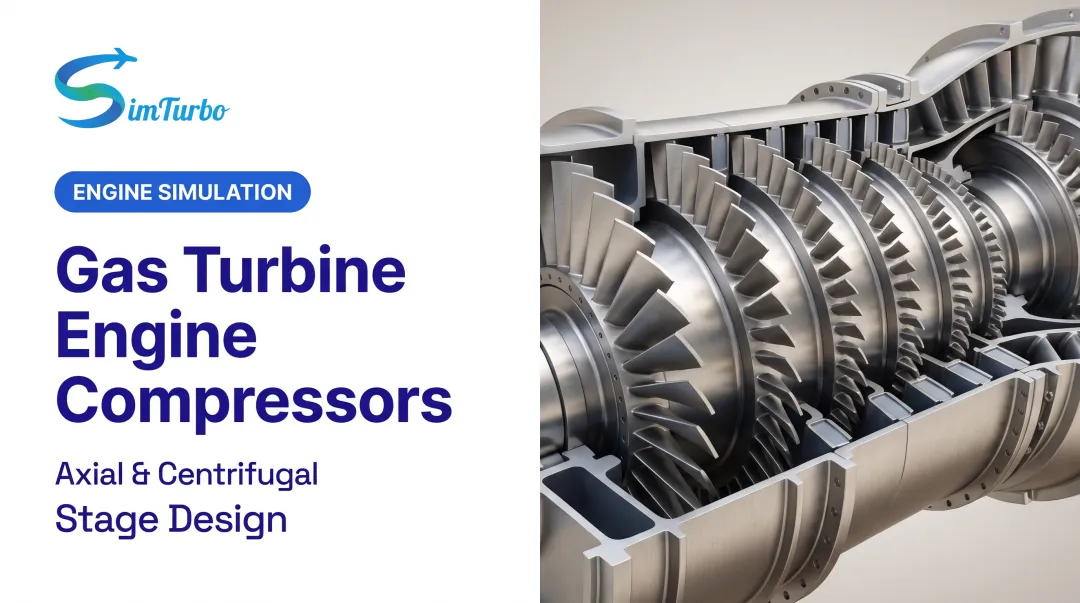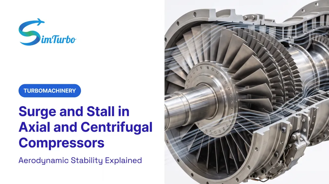
This article covers the signals, instrumentation, and interpretation methods that enable engineers to distinguish real surge from process noise—and prevent costly damage before multiple destructive cycles accumulate.
Key Takeaways
- Surge detection captures rapid changes in flow, pressure, or temperature at the compressor flanges.
- Systems must respond within 100-500 milliseconds to identify individual surge cycles before damage accumulates.
- Reliable detection combines multiple independent signals rather than a single measurement.
- Detection systems alarm on surge events but don't replace anti-surge control; they verify effectiveness and trigger emergency responses.
What You Need to Detect Compressor Surge
Reliable surge detection requires specific instrumentation, signal processing capability, and proper physical placement near the compressor. Detection is not a threshold alarm on a single absolute value; it recognizes rapid oscillation patterns that distinguish surge from normal process variation.
Instrumentation and Signal Types
The primary measurements for surge detection include:
- Suction and discharge pressure transmitters – Capture rapid pressure oscillations during flow reversal
- Flow measurement devices – Orifice differential pressure, venturi, or ultrasonic meters that track sharp flow decreases and recoveries
- Suction temperature sensors – Detect rapid temperature increases during surge events
- Motor current or power monitoring – Substitute when direct flow measurement is unavailable
Each instrument must update faster than 200 milliseconds and sit as close as possible to the compressor flanges. Volume between the compressor and sensor acts as capacitance, smoothing rapid surge oscillations and delaying detection or preventing it entirely.
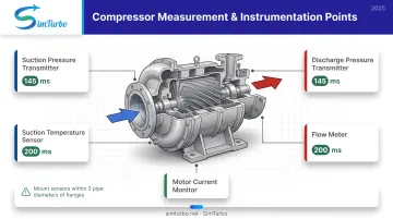
One Rosemount pressure transmitter example achieves 145 ms total response (45 ms nominal dead time, 22 updates/second). User damping settings can still add 0–60 seconds of delay and wipe out the surge signature if left unchecked.
Signal Processing Hardware
Detection systems need:
- Logic solvers with total scan time under 100 ms
- Simultaneous processing of frequency and analog inputs
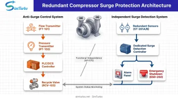
- Independent operation from the anti-surge control system
That independence, required under API 670 guidance, keeps detection alive if the anti-surge controller fails so alarms and emergency responses still fire.
Two common architectures meet this requirement:
- Dedicated surge detection controllers that operate standalone with their own sensors and logic
- Redundant PLC or DCS platforms with segregated programming, separate sensor inputs, and independent outputs
The detection system monitors rate of change and oscillation amplitude. It often requires both flow and pressure channels to show surge-like behavior before incrementing the cycle counter and issuing outputs such as alarms, fast recycle opening, or compressor-driver trips.
Methods to Detect Compressor Surge
Surge manifests as rapid oscillations in thermodynamic and mechanical measurements. Detection systems monitor rate-of-change patterns rather than absolute threshold crossings, distinguishing surge from slower process upsets or normal turbulence.
Method 1: Flow Reversal Detection
How it works:
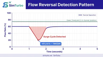
Flow reversal detection watches compressor inlet or discharge flow for a rapid decrease followed by recovery, a characteristic "valley" signature that marks each surge cycle.
Tools and indicators:
High-speed flow transmitter (orifice ΔP, venturi, or mass flow meter) with update rate ≤200 ms, plus a signal differentiator to calculate rate of change.
Implementation steps:
- Record flow signal during stable operation to establish baseline noise envelope
- Set rate-of-change threshold 2-3× above normal process variation
- Configure detection logic to trigger when flow drops by a defined percentage within milliseconds, then recovers
- Validate thresholds by reviewing historical surge event recordings or commissioning surge tests
Advantages and limitations:
Flow differential pressure normally provides the most revealing surge signature and responds fastest to surge onset. However, flow measurement may not be available on all compressor stages, and signal noise from turbulent flow or poor piping installation can cause false positives.
Method 2: Discharge Pressure Oscillation Detection
How it works:
Discharge pressure monitoring looks for rapid decrease-and-recovery cycles that signal pressure-ratio collapse during surge.
Tools and indicators:
Fast-response pressure transmitter at the discharge flange and a pressure rate-of-change calculator.
Implementation steps:
- Record pressure signal during stable operation to characterize normal dynamics
- Configure the detector to identify pressure drops exceeding normal upset rates
- Adjust thresholds for compressor volume and piping: larger volumes dampen oscillations and slow detection
- Test by comparing pressure signal timing against flow signal during historical events
Advantages and limitations:
Pressure transmitters are typically already installed for control purposes, providing a cost advantage. However, discharge volume acts as capacitance that smooths and delays the surge signature, making pressure slower to respond than flow.
Outlet pressure detection identifies severe surge late. By the time pressure oscillations are clear, damage is already occurring.
Method 3: Multi-Variable Pattern Recognition
How it works:
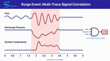
This approach combines flow, discharge pressure, suction temperature, and optional vibration signals to detect surge through correlated oscillation patterns across multiple measurements.
Tools and indicators:
Integrated detection system accepting 3-5 independent analog or frequency inputs, with pattern recognition logic that compares signal phase relationships.
Implementation steps:
- Configure the system to monitor all available signals simultaneously
- Establish correlation patterns: true surge shows in-phase oscillations across flow and pressure with temperature spikes
- Set detection to require 2-of-3 signal confirmations within the same time window
- Use the multi-variable approach to distinguish surge from single-point instrument failure or process upset
Advantages and limitations:
Multi-variable detection provides the highest reliability and lowest false-alarm rate by cross-confirming surge conditions. It also offers continued detection capability if one transmitter fails. The trade-off is higher instrumentation investment and more complex configuration.
How to Interpret Detection Results
Detection system output ranges from no alarm during normal operation, through incipient surge warnings, to confirmed cycling surge. Your response must escalate based on surge frequency and severity.
Misinterpreting detection signals risks under-response that allows compressor damage, or over-response with unnecessary emergency shutdowns and production loss.
Normal Operation / No Detection
Signal characteristics:
Flow, pressure, and temperature measurements show normal process variability. Rate of change stays within the established noise envelope, and no oscillation patterns appear.
Recommended action:
Continue operation. The detection system remains active and continues monitoring. Periodically verify system functionality through manual test features or simulation inputs. Platforms such as SimTurbo allow engineers to practice surge detection configuration and response procedures in a safe virtual environment before deployment on operating equipment.
Incipient Surge / Single Cycle Detection
Signal characteristics:
The detection system identifies one surge cycle—a rapid flow decrease and recovery or pressure oscillation—but the event does not repeat within the monitoring window (typically 30-60 seconds).
What it means:
The operating point briefly crossed the surge limit due to a process upset (flow reduction, pressure spike, temperature transient), but anti-surge control or process recovery moved operation back to a stable region.
Recommended action:
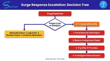
- Generate alarm for operator awareness
- Log the event with timestamp and operating conditions
- Review what caused the operating point to approach the surge line
- Do not initiate emergency shutdown for a single isolated event
- Consider adjusting anti-surge control margin if single-cycle events become frequent
Confirmed Surge Cycling / Multiple Detections
Signal characteristics:
The detection system records 2-3 surge cycles within a 60-second window, indicating the compressor has entered unstable operation. The process and control system cannot maintain operation right of the surge limit.
What it means:
This is a dangerous condition. Each cycle hammers thrust bearings and seals, internal temperature rises, and mechanical damage accumulates rapidly. Axial machines may show measurable damage after only a few cycles.
Recommended action:
- Execute emergency response per site procedures
- Force anti-surge recycle valve fully open
- Reduce compressor speed if variable-speed drive is available
- Trip the compressor if surge cycling continues beyond 3-5 cycles
- Investigate root cause before restart: anti-surge control failure, process blockage, instrument failure, or operation beyond design envelope
Out-of-Spec / Detection System Failure
Signal characteristics indicating system malfunction:
- Loss of signal from transmitters
- Detection logic faults
- Conflicting signals (one sensor shows surge while others show normal operation)
What it means:
Faulty detection provides false security while leaving the compressor unprotected.
Recommended action:
- Switch to backup detection channel if redundant system is installed
- Reduce compressor loading to a conservative operating point away from surge risk
- Repair or replace failed detection components before returning to full-capacity operation
- Investigate whether instrument vibration, electrical interference, or calibration drift caused the failure
Common Errors in Compressor Surge Detection
Detection reliability depends on proper system design, installation, and configuration. Common implementation mistakes lead to either missed surge events or excessive false alarms that erode operator trust.
Installing Instruments Too Far from Compressor
The problem:
Pressure or flow transmitters placed many pipe diameters from the compressor flanges—or downstream of large volumes such as vessels and piping networks—add signal damping and time delay. Volume between the compressor and sensor acts as capacitance that smooths rapid surge oscillations, slowing detection or blocking it entirely.
Guidance:
Mount sensors as close as possible to compressor suction and discharge flanges. Avoid installation points downstream of anti-surge recycle junctions or upstream of suction separators, where process volumes dampen the signal.
Setting Detection Thresholds Based on Assumptions Rather Than Data
The problem:
Detection thresholds (rate-of-change limits, oscillation amplitude) are often set from generic literature values or other sites instead of the machine’s own behavior.
Every compressor and process pairing has a unique surge signature shaped by machine design, piping volumes, gas properties, and operating conditions. Generic settings produce false alarms or missed detections.
Recommended approach:
- Record high-speed data from commissioning surge tests (or historical surge events)
- Analyze actual signal behavior before setting thresholds
- Document the threshold rationale for later review
One published example used a 20% span drop per 100 ms threshold, but that figure was installation-specific, not a universal benchmark.
Failing to Distinguish Detection from Control Functions
The problem:
Some installations incorrectly combine surge detection logic within the anti-surge control system, violating API 670 functional independence requirements. If the anti-surge controller fails (software fault, hardware failure, configuration error), the combined system loses both control and detection simultaneously, leaving the compressor completely unprotected.
Correct architecture:
- Operate detection on independent hardware or a segregated redundant logic solver
- Monitor independent sensor inputs (or redundant shared sensors)
- Provide alarm and shutdown outputs separate from the anti-surge valve command
Safety and Best Practices
Surge detection systems protect high-value assets and personnel. They need design, testing, and maintenance practices that keep them reliable over years of service.
Design for Functional Independence and Redundancy
API 670 requirement:
Surge detection must be functionally independent from anti-surge control: separate sensors, separate logic processing, or redundant controller architecture with segregated programming.
Recommended redundant measurement strategy:
- Use independent flow and pressure measurements so detection continues if one transmitter fails
- Configure logic to alarm if signals disagree, indicating an instrument fault
- Ensure detection remains active during anti-surge controller testing, commissioning, or maintenance
Test Detection System Regularly with Simulated Inputs
Detection systems may sit dormant for months or years between actual surge events. Untested systems suffer from hidden failures such as sensor drift, logic errors, and wiring faults.
Testing approach:
- Inject simulated surge signatures (ramp signals that mimic flow or pressure oscillations) at the instrument level, or use software simulation inputs
- Verify detection logic triggers correctly and alarm/shutdown outputs activate
- Document test results
SimTurbo simulation environments let control engineers practice surge detection configuration and response in a safe virtual setting. The platform includes real-time compressor map overlays, surge-margin visualization, and transient stall/surge scenarios so teams can validate detection logic before deploying it on operating equipment.
Maintain Instrument Calibration and Inspect Installation
Detection accuracy depends on instrument health. Transmitter calibration drift, impulse line plugging, vibration-induced noise, or electrical interference degrades signal quality.
Maintenance guidance:
- Include detection system instruments in routine calibration schedules (annually or per manufacturer recommendation)
- Inspect impulse line connections for leaks or blockages that isolate transmitters from the process
- Verify sensor mounting hardware is secure and isolated from excessive vibration
- Review signal trend data for gradual degradation patterns
Poorly maintained detection systems generate false alarms that train operators to ignore warnings, defeating the system's protective purpose.
Conclusion
Reliable surge detection depends on fast-response instrumentation located close to the compressor, signal processing that distinguishes surge oscillations from normal process variation, and interpretation logic that escalates response from single-event alarms to emergency shutdown for cycling surge.
Detection systems serve as an independent verification layer above anti-surge control. Combining detection with operator training, including simulation-based practice using platforms such as SimTurbo, strengthens protection for critical compression assets.
Frequently Asked Questions
What causes compressor surge?
Surge occurs when compressor flow decreases below the minimum sustainable level for a given pressure ratio, causing compressed gas energy to exceed the energy the rotating impeller can maintain, resulting in rapid flow reversal. Common triggers include downstream demand reduction, discharge blockage, anti-surge control failure, or operating beyond the design envelope.
How harmful is compressor surge to a turbocharger?
Surge is highly damaging to all compressor types including turbochargers. Each surge cycle creates abnormal thrust loads, hammers bearings and seals, causes temperature spikes, and generates high vibration. Even a single severe surge can cause immediate bearing or seal failure in some designs.
What is the surge point in a compressor?
The surge point is the minimum flow rate at which a compressor can sustain stable operation for a given pressure ratio and speed. This point defines the left-hand boundary of stable operation on the compressor performance map. Operating at or left of the surge point results in flow reversal and unstable cycling.
What are surging and choking in a compressor?
Surging and choking are opposite limits of the compressor operating range. Surge hits at low flow and high pressure ratio with flow reversal; choke hits at high flow when gas velocity reaches sonic conditions. Both block process requirements and risk mechanical damage.
How fast do you need to detect compressor surge?
Detection systems must respond within 500 milliseconds total "screw-to-screw" time (input signal change to output activation), with instrument response under 200 ms and logic solver scan under 100 ms. That speed catches individual surge cycles (typically 1-5 seconds centrifugal, 3-20 seconds axial) before multiple damaging cycles accumulate.
Can you prevent surge with detection alone?
No. Detection identifies surge after it occurs and triggers alarms or emergency responses, but it does not prevent surge. Prevention belongs to anti-surge control systems that modulate recycle valves to keep the operating point right of the surge limit. Detection is the backup layer if control fails.