This guide walks you through gas turbine system essentials: definition and operating principles, core components, major configurations, real-world applications, design trade-offs, and the simulation tools that validate performance before hardware testing. By the end, you'll have a clear framework for understanding, analyzing, and designing GT systems for academic or professional projects.
Key Takeaways
- GT systems convert fuel into mechanical power or thrust through compression, combustion, and expansion in a continuous Brayton cycle
- Five core components (inlet, compressor, combustor, turbine, nozzle) work in sequence to process airflow and extract energy
- Turbojets, turbofans, turboprops, and turboshafts power aircraft; industrial turbines drive generators and marine vessels
- High power-to-weight ratio and fuel flexibility make GT systems dominant in aviation and power generation
- Validated simulation platforms let engineers iterate designs, match components, and optimize controls before physical testing
What Is a GT (Gas Turbine) System? – Definition & Overview
A gas turbine (GT) system is a continuous-flow heat engine that converts chemical energy in fuel into mechanical power or thrust. It operates on the Brayton thermodynamic cycle.
Unlike piston engines with intermittent combustion strokes, or steam turbines that need external boilers, a GT system works in steady open flow. It ingests air, compresses it, burns fuel at constant pressure, and expands the hot gases through a turbine to produce useful work.
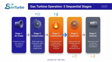
The fundamental operating sequence:
- Air intake – Ambient air enters through an inlet
- Compression – A compressor raises air pressure and temperature
- Combustion – Fuel mixes with compressed air and burns at controlled temperature
- Expansion – Hot gases expand through a turbine, driving the compressor and delivering net shaft power or jet thrust
- Exhaust – Spent gases exit through a nozzle
GT systems dominate aviation, power generation, and marine propulsion. They deliver high power density and reliability without the vibration of reciprocating engines, and they run on natural gas, diesel, or jet fuel depending on the application.
Historical milestone: The first successful turbojet flight occurred on August 27, 1939, when Hans von Ohain's HeS 3B engine powered the Heinkel He 178 in Germany.
Independently, Frank Whittle patented his turbojet concept in 1930, and a Whittle-powered aircraft first flew in May 1941. Those parallel breakthroughs launched the gas turbine era that now powers nearly every modern airliner and many naval vessels.
Key Components of a Gas Turbine System
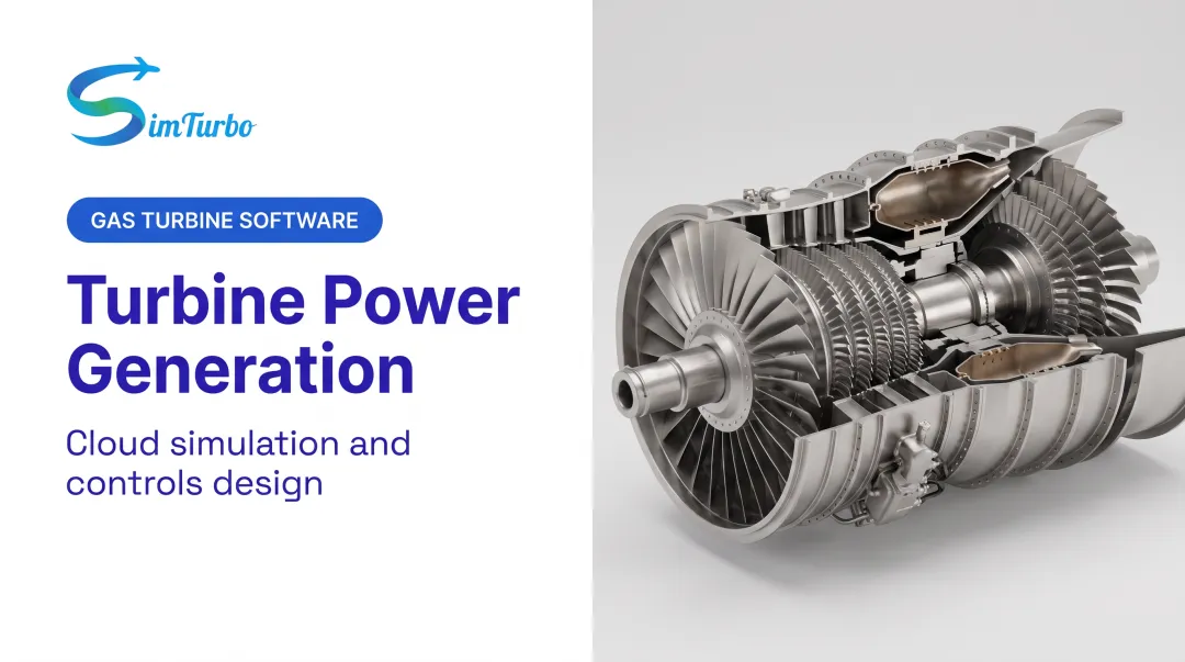
Every gas turbine system comprises five essential components that work in sequence to process airflow and extract energy.
Inlet/Air Intake
The inlet captures and conditions incoming air, ensuring smooth, low-loss flow to the compressor. Design requirements vary sharply by application:
- Subsonic aircraft use short, smooth inlets with thick lips to minimize drag and pressure losses
- Supersonic military jets require sharp-lipped inlets with compression shocks (generated by cones or hinged ramps) to decelerate flow to subsonic speed before the compressor
Variable-geometry inlets, such as those on the F-14 and F-15, adjust shock positioning across the flight envelope. However, hinge leakage can make variable geometry unsuitable for hypersonic flight where extreme temperatures challenge sealing materials. Total-pressure recovery (the ratio of compressor-face total pressure to freestream total pressure) is the key performance metric.
Compressor
The compressor increases air pressure and temperature before combustion, directly raising thermal efficiency. Two main types dominate:
- Axial-flow compressors use multiple rotating and stationary blade rows (stages) to achieve high pressure ratios and efficiency
- Centrifugal compressors use a single impeller stage to accelerate air radially outward, then diffuse it in a volute
The GE9X axial compressor delivers greater than 60:1 overall pressure ratio and 27:1 core pressure ratio. NASA-tested compact centrifugal units achieved 4.68:1 pressure ratio; ASME reports stages with pressure ratio ≥4 are common in helicopter engines, where compactness and weight matter more than peak efficiency.
Pressure ratio, efficiency, and surge margin define compressor performance. Surge, a flow instability that can damage the engine, occurs when the compressor operating point moves too far left on its characteristic map.
Combustor (Combustion Chamber)
Fuel is injected and mixed with a portion of the compressed air, then ignited and burned at carefully controlled temperatures. Lean-combustor research focuses on maintaining flame stability while reducing nitrogen-oxide (NOx) emissions across varying loads.
Operating temperatures:
- Advanced turbine inlet temperatures reach 2,600°F (approximately 1,425°C) in modern power turbines
- ASME studies analyze turbine-entry conditions spanning 1,200–1,600°C depending on engine class and cycle design
These temperatures exceed the melting points of metal alloys, requiring advanced materials and cooling strategies downstream.
Turbine
The turbine extracts energy from hot, high-pressure combustion gases to serve two roles:
- Drive the compressor – Turbine work must exceed compressor work for the engine to produce net output
- Produce useful output – Remaining energy becomes shaft power (for generators or propellers) or kinetic energy (for jet thrust)
Turbine blades operate in the hottest part of the engine, well above the melting point of traditional nickel-based superalloys. Film cooling routes compressor bleed air through internal passages and out surface holes, shielding blades from direct gas contact.
GE's ceramic matrix composite (CMC) turbine blade weighs about one-third that of the metal blade it replaces, needs no second-stage air cooling, and tolerates temperatures hundreds of degrees above legacy alloys.
Exhaust Nozzle
The nozzle accelerates exhaust gases to produce thrust (in propulsion) or efficiently directs flow for energy extraction (in power generation).
Nozzle types:
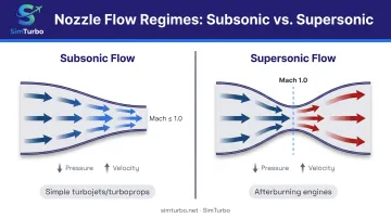
- Converging nozzles accelerate subsonic flow and are used in simple turbojets and turboprops with fixed geometry
- Converging-diverging nozzles expand flow beyond the sonic throat to supersonic speeds and are required in afterburning turbojets and turbofans
Variable-geometry nozzles accommodate wider airflow ranges at the cost of added weight and mechanical complexity.
Types of Gas Turbine Systems
GT systems are categorized by application and internal configuration, each optimized for specific thrust, efficiency, or power-delivery requirements.
By Application & Cycle Architecture
Turbojet:
Thrust comes primarily from hot core exhaust. This simple, lightweight layout powered early jet fighters and high-speed aircraft such as the T-38 trainer.
Turbofan:
A turbine-driven fan adds bypass-air thrust around the core. Most modern airliners use high-bypass turbofans because they combine strong thrust with strong fuel efficiency.
Low-bypass afterburning turbofans power military jets such as the F-14, trading some efficiency for higher specific thrust.
Turboprop:
Turbine shaft power drives a propeller for efficient low-speed flight. Transports such as the C-130 and UAVs such as the MQ-9 Reaper (900 shp Honeywell TPE331-10GD) use turboprops when range and loiter time matter more than speed.
Turboshaft:
Almost all useful output goes through a shaft—to helicopter rotors, APUs, generators, or industrial drives—rather than exhaust thrust. These engines prioritize torque, quick response, and compact packaging.
Spool Architecture
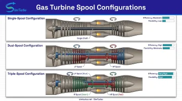
- Single-spool (von Ohain's HeS 3B): One shaft connects the compressor and turbine
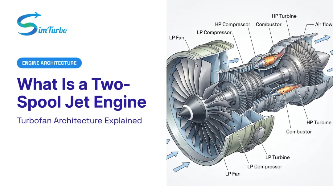
- Dual-spool (CFM56, GE90): Separate low- and high-pressure spools allow independent speed optimization
- Triple-spool (Rolls-Royce Trent 7000): Three concentric shafts add flexibility and efficiency across the operating envelope
Multiple spools improve part-load efficiency, widen the stable operating range, and let each compressor stage run nearer its best speed.
Industrial Gas Turbines for Power Generation
The same core Brayton machinery also anchors utility and industrial power plants. Cycle choice then centers on how exhaust heat is used.
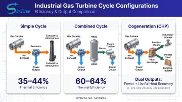
| Cycle | How exhaust heat is used | Typical role |
|---|---|---|
| Simple-cycle | Rejected to atmosphere | Peaking, rapid start |
| Combined-cycle | Drives a steam bottoming cycle | High-efficiency baseload / intermediate power |
| Cogeneration (CHP) | Supplies process steam or district heat plus power | Industrial plants, campuses, district energy |
Simple-cycle:
Siemens' SGT-800 delivers 62.5 MW at 41.1% gross efficiency—well suited to peaking duty and fast starts.
Combined-cycle:
The same SGT-800 in a 2×1 combined cycle reaches 182 MW at 60.6% efficiency. GE's 9HA family spans 448–571 MW in simple cycle (42.9–44.0% net) and can exceed 64% in combined cycle.
Cogeneration:
One gas turbine supplies electricity and useful heat together, raising total fuel utilization for process plants and district heating.
Knowing application type, spool count, and cycle architecture is the first step in matching a GT system to thrust, efficiency, or power goals—and in building a model that reflects how that system actually runs.
How Gas Turbine Systems Work
Gas turbines operate on the Brayton cycle, an idealized thermodynamic process consisting of four steps:
- Isentropic compression (inlet and compressor): Air pressure and temperature rise with no heat transfer
- Constant-pressure heat addition (combustor): Fuel burns at constant pressure, raising gas temperature
- Isentropic expansion (turbine and nozzle): Hot gases expand, extracting work with no heat transfer
- Constant-pressure heat rejection (exhaust to atmosphere): Spent gases return to ambient conditions
In a real open-cycle aircraft engine, fresh air enters continuously, combustion occurs at near-constant pressure, and exhaust gases leave the system—there is no physical heat-rejection component.
Energy Balance & Efficiency
For the engine to produce net useful work, turbine work output must exceed compressor work input. The difference becomes shaft power (for generators or propellers) or kinetic energy (for thrust).
Thermal efficiency:
- Generic simple-cycle gas turbines: 20–35% (U.S. DOE baseline)
- Modern large industrial turbines: 41–44% simple cycle (Siemens SGT-800, GE 9HA)
- Combined-cycle plants: 60.6% to greater than 64% (Siemens, GE)
Efficiency depends on pressure ratio, turbine inlet temperature, component efficiencies, and whether exhaust heat is recovered in a bottoming cycle.
For aircraft engines, fuel burn is often tracked as thrust specific fuel consumption (TSFC) rather than thermal efficiency alone.
TSFC = fuel mass flow (lb/h) ÷ thrust (lbf). NASA's teaching example gives illustrative values of 1.0 lb/(h·lbf) for a turbojet and 0.5 lb/(h·lbf) for a turbofan, showing the turbofan's efficiency advantage. Real-world TSFC varies by engine model, flight condition, and throttle setting.
Steady-State vs. Transient Operation
- Steady-state: Constant throttle, stable compressor and turbine operating points, predictable thrust or power output
- Transient: Throttle changes, startup, shutdown, load demands, and altitude shifts create time-dependent component responses
- Control needs: Systems must hold turbine inlet temperature, surge margin, and shaft acceleration within limits during those shifts
Applications of Gas Turbine Systems
Aviation
- Commercial airliners: Nearly all modern airliners use turbofans for their combination of high thrust and excellent fuel efficiency
- Military jets: Low-bypass turbofans or turbojets provide high specific thrust for supersonic flight and combat maneuvering
- Regional aircraft: Turboprops offer efficient cruise at lower speeds and altitudes
- Unmanned aerial vehicles: The MQ-9 Reaper uses a 900-shp turboprop for long endurance, while smaller UAVs often use compact turbojets
Power Generation
Gas turbines cover baseload, intermediate, and peaking duty on electric grids worldwide.
- Combined-cycle plants: Pair gas and steam turbines to reach 60%+ efficiency
- Simple-cycle units: Deliver rapid-start capability for grid stability and emergency backup
Marine Propulsion
GE's LM2500 has accumulated more than 700 units in U.S. Navy surface combatants (frigates, destroyers) and more than 16 million operating hours in commercial marine use, including cruise ships and fast ferries.
Gas turbines suit naval and high-speed commercial vessels because they offer:
- High power density in a compact package
- Rapid start for responsive maneuvering
- Low vibration compared with large reciprocating plants
Advantages and Challenges of Gas Turbine Systems
GT systems bring strong performance upsides, but operating limits and cost tradeoffs decide where they fit best.
Key Advantages
- High power density: GT systems deliver exceptional power-to-weight ratios compared to piston engines, enabling aircraft flight and compact marine installations
- Operational flexibility: Startup in minutes (vs. hours for steam plants) and rapid load response suit grid peaking and emergency backup
- Fuel versatility: Ability to burn natural gas, diesel, jet fuel, and even hydrogen (with modifications) supports diverse energy infrastructures
- Low maintenance: Fewer moving parts than piston engines reduce overhaul frequency and mechanical complexity
Primary Challenges
Part-load efficiency penalty:
A 2024 study found that inefficient part-load operation can raise specific fuel consumption more than 20% above design values. Control strategies and variable-geometry components mitigate this in modern engines.
Sensitivity to inlet air temperature:
Research shows each 1°C inlet-air-temperature increase reduces generated power by 0.6% and thermal efficiency by 0.18%. Reducing inlet temperature by 8–10°C through evaporative cooling or chillers can boost power output 8–9%.
High capital costs:
EIA data for AEO2025 shows an H-frame simple-cycle combustion turbine at $835.50/kW versus a 1×1 H-frame combined cycle at $920.90/kW (2023 dollars). Combined cycles deliver better efficiency, but they need additional steam-cycle equipment and balance-of-plant investment.
Materials engineering complexity:
Turbine blades often run hundreds of degrees above their melting points. That requires advanced superalloys, thermal barrier coatings, and intricate internal cooling, which raises development cost and manufacturing complexity.
Designing and Simulating Gas Turbine Systems
Modern GT engineering separates design-point analysis, used to size components against performance targets, from off-design analysis. Off-design work predicts behavior across the operating envelope once component choices are fixed.
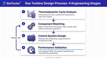
The Engineering Design Process
- Thermodynamic cycle analysis: Define pressure ratio, turbine inlet temperature, mass flow, and efficiency targets
- Component matching: Ensure compressor and turbine maps intersect at valid operating points; iterations enforce mass conservation and shaft-power balance
- Control system design: Develop fuel scheduling, surge-margin protection, temperature limiting, and transient logic
- Performance validation: Verify the design against requirements using NASA-documented techniques for corrected flow, corrected speed, pressure ratio, and efficiency
Simulation Before Hardware Testing
Physical engine testing is expensive and slow. Simulation platforms enable:
- Rapid design iteration without hardware
- Transient analysis of startup, throttle bursts, and fault conditions
- Control-law validation through closed-loop testing
- Performance mapping across altitude, Mach number, and ambient temperature
Real-time hardware-in-the-loop (HIL) testing shows the next step. NASA demonstrated this approach in 2023 on a partially turboelectric aircraft control system, pairing validated models with physical controllers to evaluate logic before flight.
SimTurbo: Component-Level Gas Turbine Simulation
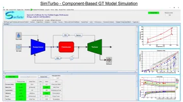
SimTurbo is a Windows-based GT simulation platform from Controls Research LLC for aerospace engineers, power systems engineers, researchers, and universities. Unlike general-purpose tools, it uses a component-based architecture rather than a black-box engine model.
Engineers drag, drop, and connect inlets, compressors, combustors, turbines, nozzles, shafts, PID controllers, limiters, actuators, and sensors. That setup supports real-time study of Brayton-cycle behavior, compressor-turbine matching, and control-system interaction.
Key capabilities:
- Single-spool and dual-spool turbojet configurations, plus recuperator and afterburner modeling
- Steady-state thermodynamic cycle analysis and transient simulation (startup, throttle changes, stall, surge)
- Real-time updating of T-S diagrams, P-V plots, component maps, and performance graphs
- Validation against NASA J85-GE-21 test data within ±2% for thrust, flow rate, temperature, and TSFC
- Data export to CSV/Excel and integration with external control validation workflows
Discounted educational licensing supports university classrooms, lab programs, and capstone projects. Aerospace and power-generation teams use the same platform for design iteration, off-design analysis, and control development before hardware prototypes.
A 30-day free trial and flexible licenses keep access practical for individual engineers and research groups: monthly ($59.99/month), one-year ($599), or lifetime ($5,999).
Frequently Asked Questions
What does GT stand for in GT system?
GT stands for "Gas Turbine," referring to the turbine that extracts energy from expanding combustion gases. The term covers the full engine—compressor, combustor, turbine, and related parts—that converts fuel into mechanical power or thrust.
How does a gas turbine system work?
A gas turbine compresses incoming air, mixes it with fuel and ignites it at constant pressure, then expands the hot gases through a turbine that drives the compressor and produces net output. Exhaust gases leave continuously, completing the open Brayton cycle.
What are the main types of gas turbine systems?
Turbojets generate thrust from core exhaust; turbofans add bypass air for efficiency; turboprops use shaft power to drive propellers; turboshafts deliver torque for helicopters or generators. Industrial stationary turbines power electric grids in simple-cycle, combined-cycle, or cogeneration configurations.
What industries use gas turbine systems?
Aviation relies on turbofans, turbojets, and turboprops for propulsion, while utilities use industrial turbines for baseload, intermediate, and peaking power. Ships and oil-and-gas operators use turboshafts and GT-driven compressors where compact, high power matters.
What are the advantages of gas turbine systems?
High power-to-weight ratio, fast startup, and rapid load response suit aircraft and compact power plants. They run on natural gas, diesel, jet fuel, or hydrogen, and fewer moving parts mean simpler maintenance than piston engines.
How efficient are gas turbine systems?
Simple-cycle efficiency typically ranges 30–40% for aero-derivative and industrial turbines, and about 41–44% in modern large units. Combined-cycle plants reach 60–64% by recovering exhaust heat in a steam cycle. Results depend on pressure ratio, turbine inlet temperature, and component design.
Ready to explore gas turbine simulation in depth? SimTurbo offers a 30-day free trial with full access to component-level modeling, real-time transient analysis, and validated thermodynamic cycle tools used by aerospace engineers and universities worldwide. Visit SimTurbo or call (779) 390-4786 to start designing, analyzing, and optimizing GT systems today.