Droop control is a fundamental proportional control strategy used in both electrical power systems and mechanical governor systems. It enables multiple generators or engines to share load proportionally and maintain stability—without direct communication between units. The elegance lies in its simplicity: as system frequency or speed rises, each unit automatically reduces its power output according to a pre-set slope. This inverse relationship creates a self-regulating system that has remained a cornerstone of grid stability, microgrid operation, and gas turbine control for decades.
This article walks through the definition and working principles of droop control, explores the types and applications across power generation and gas turbine systems, compares droop with alternative control modes, and examines how engineers simulate and validate droop strategies before deployment.
Key Takeaways
- Links power output inversely to frequency or speed, enabling communication-free load sharing among parallel units
- Typical droop settings range from 3–5% for grid-connected systems, balancing responsiveness with stability
- Delivers primary frequency response within seconds; secondary control is still required to restore nominal frequency
- Engineers validate droop behavior through simulation, field testing, and hardware-in-the-loop environments before live deployment
What Is Droop Control?
How Droop Control Works
Droop control is a proportional control strategy in which a generator's or engine's power output decreases (or "droops") as system frequency or shaft speed increases.
Rather than holding a fixed frequency or speed setpoint, droop sets an intentional linear relationship: higher load means lower frequency, and lower load means higher frequency.
This characteristic allows multiple units to share load proportionally without needing direct communication or a central dispatch controller. Each unit responds locally to the same system frequency, adjusting its contribution based on its own droop setting.
Key distinctions:
- Electrical power systems (generator droop): Links active power output to grid frequency using a frequency-power (P-f) relationship
- Mechanical systems (governor droop): Links fuel flow to shaft speed in gas turbines, diesel engines, and other prime movers
Both implementations rely on the same principle: an inverse proportional relationship that stabilizes operation and enables parallel load sharing.
The Droop Characteristic Curve
The droop characteristic is represented graphically as a straight line on a frequency-versus-power (or speed-versus-fuel) plot. As frequency decreases from no-load to full-load conditions, power output increases proportionally.
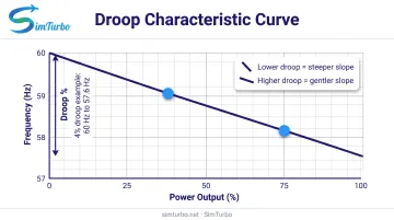
Droop percentage defines the slope of this line. For example, a 4% droop means frequency will drop by 4% of nominal as the unit moves from no-load to full-load operation.
Worked example (from Woodward governor documentation):
A gas turbine with 3% droop operates at a nominal speed of 1,800 rpm (equivalent to 60 Hz in a synchronized generator).
At no fuel (no load), the governor reference is set to 1,854 rpm (61.8 Hz). At maximum fuel (full load), the reference drops to 1,800 rpm (60 Hz). The 54 rpm difference is 3% of 1,800 rpm.
If the governor only uses half its fuel range, the effective span becomes 1,827–1,800 rpm (60.9–60 Hz), and the effective droop is now smaller.
How droop percentage affects behavior:
- Lower droop (e.g., 2%): Tighter frequency regulation, faster response, but higher risk of instability or hunting
- Higher droop (e.g., 5%): Greater stability, smoother response, but larger steady-state frequency deviation under load
- Matched droop settings: Units with identical droop percentages share load in proportion to their ratings
Key Terminology
- Nominal frequency / rated speed: The system's normal operating frequency (e.g., 60 Hz, 50 Hz) or the engine's rated speed at full load
- Speed reference / frequency reference: The governor or controller's internal target, which shifts according to the droop characteristic as load changes
- No-load speed: The speed or frequency reference at zero fuel or zero power output
- Full-load speed: The speed or frequency reference at maximum fuel or rated power
- Droop rate / droop coefficient: The percent change in speed (or frequency) per unit change in power; often expressed as a percentage or in units like MW/Hz
- Speed droop: Used in mechanical systems (gas turbines, engines) where governor action controls shaft speed via fuel flow
- Frequency droop: Used in electrical systems (synchronous generators, inverters) where controller action adjusts active power output based on grid frequency
Historical Context and Importance
Droop control emerged as engineers sought stable, decentralized methods for operating multiple generators or engines in parallel. Early steam and diesel engine governors used mechanical droop mechanisms (spring-and-linkage systems) that produced a speed-versus-fuel slope.
In power electronics, Chandorkar, Divan, and Adapa's 1993 IEEE paper on parallel-connected inverters in standalone AC systems showed that inverter-based systems could emulate synchronous generator droop behavior.
By 2007, IEEE work confirmed that local frequency and voltage droop let parallel inverters run without common control circuitry or communications.
Why droop remains critical today:
- Grid stability: Provides primary frequency response when generation or load suddenly changes, helping arrest frequency decline within seconds
- Microgrid autonomy: Enables islanded microgrids to operate without centralized dispatch or high-speed communication links
- Gas turbine governor control: Stabilizes fuel-speed loops and allows multiple turbines to share mechanical load on a common shaft or electrical bus
- Renewable integration: Modern grid-forming inverters use droop algorithms to emulate synchronous generator behavior, supporting grid stability as renewables displace conventional generation
How Droop Control Works
The Basic Mechanism
Droop control adjusts fuel input (in mechanical systems) or power output (in electrical systems) based on the error between a speed or frequency reference and the actual measured value. The key difference from fixed-setpoint control is that the reference itself shifts as the controlled output changes.
Self-regulating principle:
When system load increases and frequency drops, all units operating with droop control detect the lower frequency and automatically increase their power output. The amount each unit contributes depends on its droop slope and capacity. Units with identical droop settings share the additional load proportionally, without needing to communicate or coordinate.
Example:
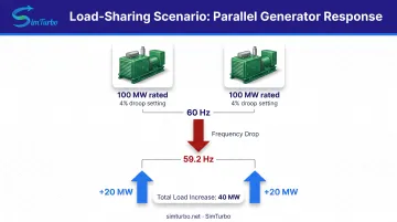
Two synchronous generators, each rated 100 MW and set to 4% droop, operate in parallel on an isolated grid at 60 Hz. A sudden 40 MW load increase causes grid frequency to drop to 59.2 Hz. Each generator increases output by 20 MW, sharing the load equally because their droop slopes are identical.
Mathematical Foundation
The basic droop relationship for frequency droop (active power control in electrical systems) is:
f = f₀ - m(P - P₀)
Where:
- f = actual system frequency (Hz)
- f₀ = nominal frequency at reference power (Hz)
- m = droop coefficient (Hz per MW or Hz per pu)
- P = actual power output (MW or pu)
- P₀ = reference power output (MW or pu)
For speed droop in gas turbine governors, the equivalent formula is:
N = N₀ - k(F - F₀)
Where:
- N = shaft speed (rpm)
- N₀ = no-load speed reference (rpm)
- k = droop coefficient (rpm per unit fuel position)
- F = fuel flow or valve position (pu or %)
- F₀ = reference fuel position (pu or %)
Numerical example (5% droop on a 60 Hz, 100 MW generator):
- Nominal frequency: 60 Hz
- Full-load frequency: 60 Hz × (1 - 0.05) = 57 Hz
- Droop coefficient: m = (60 - 57) / 100 = 0.03 Hz/MW
If the generator operates at 50 MW, frequency will be:
f = 60 - 0.03 × 50 = 58.5 Hz
If load increases to 80 MW, frequency drops to:
f = 60 - 0.03 × 80 = 57.6 Hz
Load Sharing Among Multiple Units
When multiple generators or engines with identical droop settings operate in parallel, they share load changes in proportion to their ratings. The math is straightforward: each unit's response to a frequency deviation is determined by its droop slope, so equal slopes produce proportional sharing.
Example:
- Unit A: 250 kVA inverter, 0.6% droop
- Unit B: 125 kVA diesel generator, 0.6% droop
- Unit C: 187.5 kVA inverter, 0.6% droop
In a test conducted by NREL, these three units with equal droop settings shared a load increase proportionally, though limited frequency-reference precision caused minor tracking error. Matching droop percentages enables decentralized, communication-free sharing.
What happens with unequal droop settings?
If Unit A has 4% droop and Unit B has 6% droop, Unit A will pick up a larger share of any load increase because its frequency response is steeper. This is sometimes intentional (engineers can prioritize certain units by assigning lower droop values), but it prevents perfectly proportional sharing.
Droop Control in Power Systems vs Gas Turbines
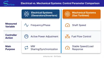
| Domain | Measured variable | Controller action | Main purpose | Evidence source |
|---|---|---|---|---|
| Synchronous generator / inverter | Frequency or phase angle | Adjusts active power reference; Q-V droop adjusts voltage/reactive output | Synchronization, MW sharing, reduced circulating reactive power | NREL GFM model |
| Gas turbine governor | Shaft speed | Changes fuel command; reference decreases as fuel/load rises | Stable speed/load response and parallel loading | Woodward Application Note |
Electrical systems:
Synchronous generators measure grid frequency. When frequency drops, the droop controller increases active power output. On a stiff utility grid, frequency is imposed by the larger system, so adjusting the governor reference changes generator loading rather than grid frequency.
Mechanical systems:
Gas turbine governors measure shaft speed. When a load increase slows the turbine, the governor increases fuel flow. The droop characteristic ensures the new steady-state speed is slightly lower than the no-load reference, preventing oscillation and enabling stable parallel operation.
Woodward documentation permits multiple engines in droop on an isolated bus, or all units except one in droop with a single isochronous unit maintaining frequency, provided that unit has sufficient reserve capacity.
Response Time and Stability
Droop control provides primary frequency response on timescales of seconds. NERC evaluates initial response by averaging measured power output from 20 to 52 seconds after an event begins. This window reflects governor actuation, fuel system dynamics, and engine inertia, not a universal response time for all equipment.
Stability tradeoff:
- Lower droop (2%): Faster, more aggressive response, but Woodward reports this may be insufficient for stability in many applications
- Moderate droop (4%): Generally adequate for most gas turbine and generator applications; balances responsiveness and damping
- Higher droop (5–6%): Greater stability margin, but larger steady-state frequency deviation
Excessive droop can also create problems. After a unit separates from a bus, high droop may allow unloaded overspeed, risking a turbine trip.
Secondary and tertiary control:
Droop intentionally permits steady-state frequency offset. To restore an isolated system to nominal frequency after a large load change, a secondary control mechanism is required. This can be:
- An isochronous unit with reserve capacity that holds frequency constant while droop units share load
- A supervisory automatic generation control (AGC) system that adjusts setpoints centrally
- Integral action added to the droop controller (though this sacrifices the pure proportional characteristic)
Types of Droop Control
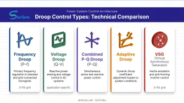
Droop control takes several forms, depending on whether the goal is to regulate active power, reactive power, or both:
| Droop Type | Controlled Parameter | Typical Application | Droop Range |
|---|---|---|---|
| Frequency droop (P-f) | Active power vs. frequency | Sync generators, diesel/gas gensets, grid-forming inverters | 3–5% grid-connected; ~0.6% in some microgrids |
| Voltage droop (Q-V) | Reactive power vs. terminal voltage | Inverters and generators for local voltage regulation | Application-specific |
| Combined P-Q droop | P-f and Q-V together | Microgrids, renewable inverters, hybrid systems | Application-dependent |
| Adaptive droop | Variable m and n from operating conditions | LV DC microgrids, wide load variation | Not standardized |
| Virtual synchronous generator (VSG) | Swing-equation inertia plus droop | Inverter systems that need inertia response | Droop-like steady state |
Frequency Droop (Active Power Control)
Frequency droop is the most common form. It links active power output to system frequency:
f* = f₀ − mP
where f* is the frequency reference, f₀ the no-load intercept, m the droop coefficient, and P active power.
You will see it on synchronous generators in large grids, diesel and gas gensets in industrial and backup plants, gas turbines in utility and microgrid service, and grid-forming inverters that emulate machine behavior.
Typical settings:
- 3–5% for large grid-connected generators (Woodward governor documentation)
- 0.6% in NREL’s three-source microgrid test (equal per-unit droop on all sources)
Effective slope also depends on how much of the governor’s fuel range or the inverter’s power range you actually use. A 4% setting produces a gentler effective slope if the unit only runs mid-range.
Voltage Droop (Reactive Power Control)
Voltage droop (Q-V droop) links reactive power to terminal voltage:
V* = V₀ − n(Q − Q₀)
where V* is the voltage reference, V₀ nominal voltage, n the droop coefficient, and Q reactive power.
Q-V droop limits circulating vars among parallel units, gives local voltage regulation without real-time communication, and pairs with frequency droop in full grid-forming control.
In NREL testing, one inverter used V* = 1.0119 − 0.0841Q for positive Q and V* = 1.008 − 0.0679Q for negative Q; a second unit had different measured slopes. Those coefficients are experiment-specific, not universal setpoints.
Line and transformer impedance can still skew reactive sharing. NREL needed voltage-drop compensation before Q divided as expected.
Combined P-Q Droop and Advanced Methods
Combined P-f / Q-V droop is the usual setup in modern microgrids and grid-forming inverters. Both loops run at once:
- P-f droop synchronizes phase and shares active power
- Q-V droop holds voltage and cuts circulating vars
Adaptive droop replaces fixed m and n with gains that track operating conditions—state of charge, spare capacity, or load level. A 2014 IEEE paper proposed this for low-voltage DC microgrids, where source currents often sit well below their limits and fixed droop wastes headroom.
Virtual synchronous generator (VSG) control goes further: it emulates the machine swing equation, adding virtual inertia and damping on top of droop-like steady-state behavior. Small-signal VSG models checked in PSCAD/EMTDC (IEEE, 2014) keep a droop-style frequency response but supply the inertial dynamics classical droop does not. That mix of proportional droop with differential inertia is what improves transient response in converter-heavy grids.
Applications of Droop Control
Operators use droop control wherever multiple generators, engines, or power sources must run in parallel without centralized coordination. Because each unit responds only to local frequency and voltage, the method still works when communication links are impractical or unreliable.
Power Generation and Microgrids
Conventional power grids:
In large interconnected grids, droop control provides primary frequency response. When a generator trips or load surges, all generators with active droop automatically adjust output within seconds, arresting frequency decline until slower secondary controls restore balance.
On a strong utility grid, frequency is imposed by the system. A generator's droop setting determines how much load it carries when the governor reference is adjusted. Raising the reference increases MW output; the grid frequency itself does not move.
Microgrids (grid-connected and islanded modes):
Microgrids rely heavily on droop for autonomous operation, especially during islanding. NREL's 2023 experiment demonstrated communication-free primary sharing and dispatch among two commercial grid-forming inverters and one diesel synchronous generator. Equal 0.6% droop on all three sources enabled proportional load sharing, though limited frequency-reference precision caused minor tracking error.
Renewable energy systems:
Solar and wind inverters increasingly use grid-forming control with P-f and Q-V droop to emulate synchronous generator behavior. NREL's 2022 report documented a multi-megawatt droop scheme integrating battery storage, PV, and wind. These systems support grid stability as renewables displace conventional synchronous machines.
Gas Turbine and Engine Governor Systems
Gas turbine speed governors:
Droop is fundamental to gas turbine control. When shaft speed drops due to increased load, the governor increases fuel flow. The droop characteristic ensures the new steady-state speed is slightly lower, preventing fuel-speed oscillation and enabling stable operation.
Woodward's governor documentation explicitly supports multiple engines in droop on an isolated bus, or all units except one in droop with a single isochronous unit holding frequency, provided that unit has reserve capacity.
Industrial power generation:
Aero-derivative gas turbines in industrial plants and distributed generation rely on droop for load-following and parallel operation. The same governor principles show up in marine propulsion and related shaft-driven systems. Before field changes, engineers often rehearse droop settings in simulation; tools such as SimTurbo include governor models, PID controllers, and limiters so teams can check load share and transient response against real-time engine dynamics.
Parallel Generator Operation
Diesel and natural gas gensets:
Backup power systems in hospitals, data centers, and remote facilities often run multiple gensets in parallel. Droop enables plug-and-play operation: units can be added or removed without reprogramming the others, as long as droop slopes match.
Woodward notes that engines with equal droop settings share load proportionally; unequal settings do not. This simplicity eliminates the need for complex load-sharing communication schemes.
Combined heat and power (CHP) systems:
CHP installations use droop to balance electrical output among multiple engines while meeting thermal demand. Droop allows each engine to respond locally to grid frequency or island conditions, maintaining stability without centralized dispatch.
Droop Control vs Other Control Modes
Droop is one of several governor and control strategies. Understanding alternatives clarifies when droop is appropriate and when other modes offer advantages.
Droop Control vs Isochronous Control
Isochronous control maintains constant speed or frequency regardless of load by aggressively adjusting fuel or power input. Its feedback loop has high gain and often includes integral action, driving steady-state frequency error to zero.
| Factor | Droop Control | Isochronous Control |
|---|---|---|
| Frequency behavior | Steady-state frequency changes with load | Holds constant frequency at all loads |
| Parallel operation | Natural proportional sharing when droop slopes match | Requires load-sharing communications or one designated master |
| Typical use | Multiple parallel units; grid-connected operation | Single isolated unit; communications-based island sharing |
| Tradeoff | Simple, local, communication-free; permits frequency offset | Tight frequency regulation; greater coordination complexity |
When to use isochronous:
- Single generator or engine supplying an isolated load
- Master unit in a coordinated load-sharing scheme, with other units in droop
- Applications requiring tight frequency regulation (e.g., sensitive electronic loads)
When to use droop:
- Multiple units operating in parallel without communication
- Grid-connected generators contributing to primary frequency response
- Islanded systems where some frequency deviation is acceptable
Schweitzer Engineering Laboratories (SEL) cautions that droop-only control is not recommended for certain islanded cases because it cannot actively restore frequency during events. In one industrial six-turbine island, SEL used communications-based isochronous load sharing to hold frequency and keep proportional MW distribution.
Droop Control vs Base Load and Peak Load Control
Base load control holds generator output constant, regardless of frequency or load changes. Operators use it for units that run at steady output for economic or operational reasons—steam turbines, nuclear plants, or units with must-run contracts.
Peak load (load-following) control adjusts output rapidly to track system demand. Hydro and gas turbines that can ramp quickly often run in this mode.
How droop fits:
Droop can be combined with dispatch strategies. A unit in droop mode can be dispatched to a specific basepoint (base load) or allowed to respond freely to frequency deviations (peak load). The droop characteristic determines how the unit responds to frequency; dispatch determines where it operates on the droop curve.
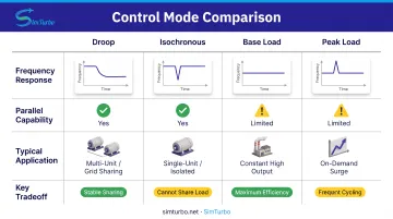
| Mode | Frequency response | Parallel capability | Typical application | Tradeoff |
|---|---|---|---|---|
| Droop | Frequency changes with load | Natural proportional sharing | Utility-parallel or multiple isolated units | Simple/local, but leaves offset |
| Isochronous | Constant frequency at all loads | Needs load-sharing scheme or master unit | Single isolated unit; coordinated sharing | Tight frequency, greater coordination |
| Base load | No inherent frequency response | Utility absorbs demand difference | Constant-output grid-parallel generation | No frequency response without dispatch |
| Peak load | Follows demand; not primary frequency response by itself | Coordinated against utility import or plant load | Load-following and demand-peak limit | Optimizes cost/tracking, not grid frequency alone |
When to Use Each Control Mode
Decision criteria:
- Single-unit island operation: Use isochronous for tight frequency regulation
- Multi-unit parallel operation (no communication): Use droop for decentralized sharing
- Grid-connected with frequency support: Use droop for primary response
- Economic dispatch / must-run units: Use base load with supervisory dispatch
- Demand management: Use peak load / load-following (including peak shaving) with economic optimization
Droop remains the foundation for decentralized, communication-free load sharing. Isochronous trades that simplicity for tight frequency hold and extra coordination; base load and peak load rely on higher-level dispatch. Modern systems often blend them: droop stabilizes locally, while supervisory controls move setpoints for economic or operational goals.
Simulating and Testing Droop Control Systems
Before deploying droop control strategies in real power systems or gas turbines, engineers validate performance through simulation, calibration, and testing. Accurate models and real-time environments reduce risk, shorten development cycles, and ensure stable operation under transient conditions.
The Role of Simulation in Control System Development
Simulation allows engineers to test droop control algorithms under load scenarios, transient events, and fault conditions without risking real equipment or grid stability. Real-time simulation is especially valuable for control-law validation, hardware-in-the-loop (HIL) testing, and operator training.
Key benefits:
- Test edge cases (e.g., large load steps, generator trips, fault conditions) safely
- Iterate control parameters (droop coefficients, gain scheduling, limiters) rapidly
- Validate that droop settings produce expected load sharing and frequency response
- Train operators on realistic system behavior before commissioning
Accurate plant models are essential. Gas turbine models must capture fuel-system dynamics, compressor/turbine maps, and inertia.
Generator models need electrical dynamics, terminal voltage, and reactive power behavior. Without that fidelity, simulation results will not predict field performance.
Simulating Droop Control in Gas Turbine Systems
Gas turbine simulation platforms model governor control, fuel flow dynamics, and shaft speed response. Engineers validate droop coefficients, speed references, and transient performance before hardware testing.
What to model:
- Governor fuel command and actuator dynamics
- Compressor and turbine matching (pressure ratio, flow, efficiency)
- Shaft inertia and mechanical power transfer
- Speed sensor measurement and filtering
- Droop characteristic (speed reference as a function of fuel position or power output)
SimTurbo is a Windows-based gas turbine simulation platform with built-in control components (PID controllers, limiters, and governor models). Engineers use it to build and check droop strategies for aerospace, marine, and power generation applications in real time.
Its component-based architecture avoids black-box limits, so you can see how control inputs change fuel flow, compressor surge margin, and shaft speed during transients.
SimTurbo's J85-GE-21 single-spool turbojet model was validated against NASA Lewis Research Center test data, with reported accuracy within ±2% for thrust, flow rate, temperature, and thrust-specific fuel consumption.
Testing and Calibration of Droop Settings
Once a droop control system is deployed, field testing verifies that simulated behavior matches actual performance.
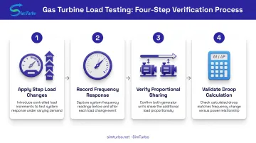
Testing procedure:
- Apply step load changes in controlled increments (e.g., 10%, 25%, 50% of rated capacity)
- Record steady-state frequency or speed before and after each load change
- Confirm units with matched droop settings raise output in proportion to their ratings
- Compare measured frequency change to power change and check it against the governor setting
Calibration:
Adjust governor or controller parameters to achieve the desired droop slope. EPRI recommends deriving droop from measured speed-reference, valve-position, and MW slopes. Plant records should include terminal voltage, current, and excitation quantities for electrical validation.
Common challenges:
- Deadband effects: Modern gas turbines may have intentional deadbands of about ±0.025% speed (±15 mHz at 60 Hz), which delay response to small frequency deviations
- Transformer and line impedance: Can interfere with reactive power sharing in Q-V droop systems; voltage-drop compensation may be required
- Effective vs. nominal droop: If a governor uses only part of its fuel range, the effective droop differs from the configured setting
Hardware-in-the-Loop and Virtual Prototyping
Hardware-in-the-loop (HIL) testing connects real control hardware to a real-time simulated plant model. The controller sends fuel or power commands to the simulation, which returns sensor feedback (speed, temperature, voltage). This allows full validation of production controller code before field deployment.
Benefits:
- Test actual control hardware timing, I/O, and fault handling
- Validate communication protocols and redundancy schemes
- Train operators on realistic system dynamics with real control interfaces
- Catch integration issues (e.g., sensor noise, actuator lag) early
Virtual prototyping:
Engineers can develop and test control logic entirely in simulation, iterating rapidly without hardware dependencies. Once validated, the control model can migrate to HIL for final verification, then to commissioning.
SimTurbo supports control validation and exports transient data to CSV, Excel, MATLAB/Simulink, and Python. Real-time runs work on standard Windows PCs (8 GB RAM minimum; multi-core recommended), so teams can exercise control algorithms under changing load without specialized hardware.
Industry practice backs this path. NASA's 2023 report documented real-time HIL testing of a partially turboelectric aircraft control design as a controller-and-plant check (not droop-specific). SEL reported about 100 simulation tests during development and factory acceptance on an islanded turbine-generator control project.
Frequently Asked Questions
What is droop in electrical systems (generator droop)?
Generator droop intentionally lowers the frequency reference as active power output rises. That inverse relationship lets multiple generators share load proportionally without communicating with each other.
How does droop control differ from isochronous control?
Droop lets frequency vary with load so units share power through local, proportional response. Isochronous holds frequency constant at all loads but needs load-sharing communication or a single master when sources run in parallel.
Why is droop control important in gas turbine engines?
Droop stabilizes the governor's fuel-speed feedback loop and prevents oscillation or hunting. It also lets multiple gas turbines share load on a common bus or shaft without real-time communication.
What are typical droop percentages used in practice?
Woodward's governor documentation lists 3–5% as the normal range for gas turbine and engine-generator applications. NREL's microgrid experiment used 0.6% equally across three sources; effective droop also depends on how much of the fuel range is used.
Can droop control be simulated in software before real-world implementation?
Yes. NREL offers a dynamic grid-forming droop model for positive-sequence studies, and EPRI covers measurement-based validation. Engineers can model and test droop strategies in simulation before commissioning.
What are the advantages and disadvantages of droop control?
Advantages: decentralized parallel operation, proportional load sharing, and simple tuning. Disadvantages: steady-state frequency offset, imperfect sharing from line impedance, need for secondary frequency control, and stability limits at very low droop.