While gas turbines may appear complex—especially to those encountering them for the first time—they consist of a manageable set of major components, each with a specific, well-defined role in the thermodynamic cycle. This article breaks down the major components of a gas turbine, explains what each does, and clarifies how they interact to produce mechanical power.
Key Takeaways
- Every gas turbine has three core components: compressor, combustor, and turbine
- Supporting systems—fuel, lubrication, cooling, control, and exhaust—keep operation safe and efficient
- Component matching and interaction set stability, efficiency, and operability
- Clear component knowledge improves design, simulation, troubleshooting, and optimization
What Is a Gas Turbine?
A gas turbine is a continuous-flow internal combustion engine that converts chemical energy in fuel into mechanical power through a three-step process: compression, combustion, and expansion. Unlike reciprocating piston engines that operate in discrete cycles, gas turbines sustain a steady flow of air and combustion gases through the engine.
Gas turbines operate on the Brayton thermodynamic cycle, in which air is compressed, heated at approximately constant pressure, and then expanded to produce work. Most modern passenger and military aircraft use gas turbine engines. They are also widely used in:
- Power generation
- Marine propulsion
- Industrial mechanical-drive systems
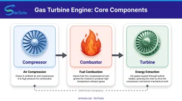
Across these applications, every gas turbine shares the same core components: a compressor, a combustor, and a turbine.
Why Understanding Gas Turbine Components Matters
Component-level knowledge matters for design, performance analysis, maintenance, and troubleshooting. When you know how each part affects the full system, optimization choices get sharper and efficiency gains become measurable.
NASA research found that increasing compressor tip clearance from 1.36% to 2.8% of blade height reduced overall efficiency by 1.5 percentage points. Small geometric changes can drive large system-level losses.
That same component insight supports several practical needs:
- Design and maintenance engineers can optimize performance and isolate faults faster
- Students and simulation users get a clearer basis for accurate modeling and analysis
- Maintenance and certification work stays aligned with airworthiness data requirements
FAA Advisory Circular 33-9 requires technical data for major repairs of critical and complex turbine-engine parts, tying component knowledge directly to safe operation.
The Three Core Components
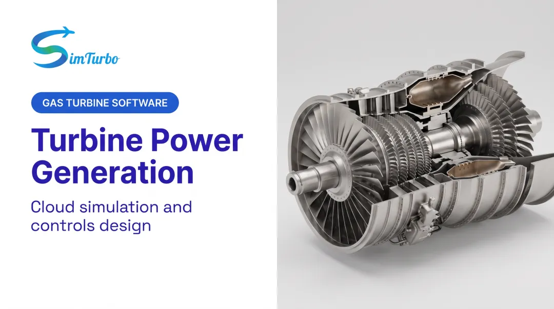
Every gas turbine has three main sections that form the engine core, also called the gas generator: the compressor, the combustor, and the turbine. Together, these three components execute the Brayton cycle and convert fuel energy into rotational mechanical work.
Compressor
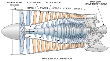
The compressor's function is to draw in ambient air and increase its pressure and temperature before it enters the combustor. Higher pressure ratios improve thermodynamic efficiency and enable more power output from a given engine size.
There are two main types of compressors:
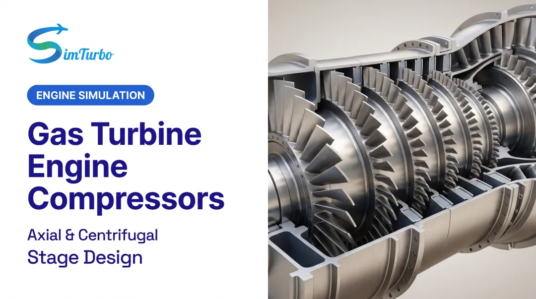
- Axial-flow compressors keep airflow parallel to the engine shaft and use multiple rotating blade rows (stages) to progressively increase pressure
- Centrifugal compressors use a spinning impeller to accelerate air radially outward, converting velocity into pressure
Axial compressors are more common in larger engines due to their higher efficiency at large mass flows and their ability to achieve high overall pressure ratios through staging.
For example, the CFM56 engine, one of the most widely used commercial turbofans, has four low-pressure and nine high-pressure compressor stages. GE's advanced GE9X high-pressure compressor has demonstrated a 27:1 pressure ratio in testing.
Compressor design, including the number of stages, blade geometry, and materials, directly impacts engine efficiency, pressure ratio, and operability. Engineers optimize blade tip clearances, airfoil profiles, and stage matching to avoid instabilities such as surge or stall.
Combustor
The combustor's role is to mix compressed air from the compressor with fuel, ignite the mixture, and produce high-temperature, high-pressure gases that drive the turbine. Combustion occurs at approximately constant pressure, with fuel nozzles atomizing or vaporizing the fuel for efficient ignition and stable burning.
There are three main combustor configurations:
- Annular combustors use continuous inner and outer liners around the engine centerline
- Can combustors consist of individual cylindrical combustion chambers arranged around the engine
- Can-annular (tubo-annular) combustors combine features of both, with separate flame tubes housed in a common outer casing
Annular combustors are common in modern engines because they offer lower weight, shorter length, and more uniform temperature distribution.
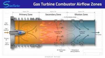
Inside the combustor, airflow is divided into three zones:
- Primary zone for fuel-air mixing and ignition
- Secondary zone for continued burning
- Dilution zone where additional air cools the gases and controls exit temperature
Only part of the compressed air participates directly in combustion; the rest cools combustor walls, mixes with hot gases, and dilutes emissions. Combustor design directly affects efficiency, emissions (particularly NOx), and flame stability across the engine's operating range.
Turbine
The turbine extracts energy from the hot, high-pressure gases exiting the combustor and converts it into rotational mechanical work. Part of this work drives the compressor through a common shaft; the remaining energy produces thrust (in aircraft engines), drives a generator (in power plants), or powers other mechanical loads.
NASA reports turbine gas temperatures above 2,000 K in high-efficiency operation, meaning turbine blades operate under extreme thermal and mechanical stress. As a result, they require advanced nickel-based superalloys and thermal barrier coatings to survive these conditions.
Modern turbines often use multiple stages to extract energy efficiently, and many engines employ multiple spools (concentric shafts rotating at different speeds). Advanced engines add spools to improve efficiency by allowing each compressor and turbine section to operate closer to its optimal speed.
Essential Supporting Systems
While the three core components perform the thermodynamic cycle, several supporting systems are critical for safe, efficient, and reliable gas turbine operation.
Fuel System
The fuel system delivers fuel to the combustor at the correct pressure, flow rate, and spray pattern. FAA guidance states that turbine power is controlled by changing fuel flow. The system must also compensate for ambient temperature, pressure, and operating conditions during acceleration and deceleration.
Key fuel system components include:
- Engine-driven pumps to pressurize fuel
- Low- and high-pressure filters to remove contaminants
- Relief and pressurizing valves to regulate pressure
- Simplex or duplex fuel nozzles that atomize fuel into a fine spray
Fuel type varies by application: Jet A is standard in aviation, natural gas and other gaseous fuels are common in power generation, and marine engines may use diesel-like fuels.
Lubrication System
The lubrication system reduces friction and wear in bearings and gears by supplying clean, temperature-controlled oil. FAA sources identify bearing cooling as a main oil function, essential in high-speed rotating machinery where heat generation is significant.
Lubrication systems typically include:
- Pressure circuits that feed oil to bearings and accessory drives
- Scavenge circuits that return oil to the reservoir
- Pumps, filters, and heat exchangers (air-oil or fuel-oil coolers)
- Thermostatic bypass valves to regulate oil temperature
Some engines use dry-sump systems with external tanks, while others use integral wet-sump reservoirs. Synthetic oils are often preferred because they exhibit lower lacquer and coke formation at high temperatures.
Cooling System
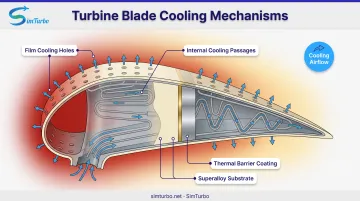
Turbine inlet temperatures routinely exceed the melting point of blade materials. Cooling systems protect blades and other hot-section parts by diverting compressed air for internal and film cooling.
NASA research describes centrifugal and thermal-expansion stresses in turbine blades, and the use of film cooling to protect blade surfaces. Thermal barrier coatings (TBCs) lower the temperature seen by the underlying superalloy. A bond coat between the TBC and the metal substrate improves adhesion and oxidation resistance.
Cooling air slightly reduces cycle efficiency, but it extends component life and supports higher turbine inlet temperatures.
Control System
The control system monitors and regulates operating parameters such as fuel flow, engine speed, temperature, and pressure to optimize performance, ensure safety, and prevent surge or overspeed.
FAA sources divide control systems into three categories:
- Hydromechanical controls use mechanical linkages and hydraulic actuators
- Hybrid electronic controls combine mechanical fuel metering with electronic supervision
- Full Authority Digital Engine Control (FADEC) uses electronic sensors, digital controllers, and electronic fuel metering
FADEC systems recognize programmed operating limits and protect against surge/stall, overtemperature, overspeed, and overpressure. Advanced simulation tools such as SimTurbo let engineers model control behavior, validate control logic, and watch real-time responses to startup, throttle bursts, and sensor failures before hardware is built.
Exhaust System
The exhaust system channels spent gases out of the turbine and may include diffusers, noise suppressors, or heat recovery equipment. NASA describes the nozzle as conducting hot exhaust and controlling thrust direction, and limiting exit velocity is a common noise-reduction approach.
In combined-cycle power plants, exhaust heat is captured by a heat recovery steam generator to produce steam for a secondary turbine cycle. The U.S. Energy Information Administration reported 2022 average heat rates of 7,146 Btu/kWh for combined-cycle systems versus about 10,000 Btu/kWh for simple-cycle gas turbines.
How Components Work Together
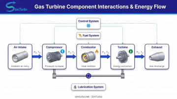
Gas turbines operate as continuous-flow machines. Air enters the compressor, is compressed and heated, then flows into the combustor where fuel is added and burned. Hot gases expand through the turbine to produce work.
Unlike reciprocating engines that run discrete intake-compression-combustion-exhaust strokes, gas turbines sustain all processes at once in different sections of the engine.
Each major stage has a defined role:
- The compressor raises pressure before combustion
- Fuel nozzles atomize fuel for efficient burning
- The turbine extracts energy to drive the compressor
The shaft connecting the turbine and compressor keeps them rotating together. The turbine must make enough power to drive the compressor and still deliver net output.
Component interaction and matching are critical for stable, efficient operation. Compressor operating points are jointly defined by mass flow and pressure ratio, and the surge line marks the stability boundary.
If the operating line moves too close to that surge line—from rapid throttle movement, combustor pressure disturbances, or control errors—the compressor can stall. Stall brings flow reversal and potential engine damage.
Tools such as SimTurbo help engineers visualize these relationships, examine component maps, and validate control strategies that hold safe margins during transient operation.
Material and Design Considerations
Gas turbine components must withstand high temperatures, pressures, and rotational speeds, requiring advanced materials and manufacturing techniques.
Hot-section materials:
- Nickel-based superalloys, often grown as single crystals to eliminate grain boundaries and improve creep resistance
- Thermal barrier coatings (TBCs) applied to turbine blades and vanes
- Bond coats between the TBC and superalloy substrate
- Emerging silicon-carbide and carbon-fiber-reinforced composites for future ultra-high-temperature applications
Design and manufacturing:
- Blade design demands precise airfoil shapes, tight clearances, and careful rotor balancing
- CFD underpins modern blade aerothermal design; Rolls-Royce adopted Hydra as its primary aerothermal CFD code in 2012
- Additive manufacturing expands cooling and geometry options; Siemens reported 3D-printed polycrystalline nickel-superalloy turbine blades in 2017
Materials research, CFD, and additive manufacturing continue to raise temperature capability, efficiency, and component life.
Frequently Asked Questions
What are the three major sections of a gas turbine engine?
The three major sections are the compressor, combustor, and turbine. The compressor raises air pressure, the combustor adds heat by burning fuel, and the turbine extracts energy from hot gases to drive the compressor and produce useful work.
What is the difference between axial and centrifugal compressors?
Axial compressors move air parallel to the engine shaft through multiple rotating blade stages, while centrifugal compressors use a spinning impeller to accelerate air radially outward. Axial compressors are more common in larger engines due to higher efficiency at large mass flows.
Why do gas turbines need a cooling system?
Turbine inlet temperatures exceed 2,000 K, far above the melting point of blade materials. Cooling air from the compressor flows through internal passages and forms protective films on blade surfaces. Thermal barrier coatings further insulate the metal and extend component life.
What role does the control system play in gas turbine operation?
The control system monitors engine parameters and adjusts fuel flow, actuators, and related variables for safe, efficient operation. It enforces limits against surge, stall, overtemperature, and overspeed during startup, acceleration, and steady-state running.
How do gas turbine components differ between aerospace and power generation applications?
Aerospace engines prioritize high power-to-weight ratio, compact size, and transient responsiveness. Power-generation engines prioritize efficiency, fuel flexibility, long service intervals, and reliability. These priorities drive differences in component materials, cooling schemes, and design margins.
What materials are used in gas turbine hot-section components?
Hot-section components use nickel-based superalloys, often as single crystals to eliminate grain boundaries. Thermal barrier coatings and bond coats protect against heat and oxidation. Advanced designs also use internal cooling passages and film-cooling holes.
A clear grasp of how the compressor, combustor, turbine, and supporting systems work together improves design, analysis, operation, and teaching outcomes. Engineers and students can model that behavior in SimTurbo when checking performance or validating control strategies.