Introduction
Recuperator design calculations size and optimize compact heat exchangers that recover waste heat from turbine exhaust to preheat compressor discharge air. When the math is sound, gas turbine cycles gain real thermal efficiency. When it is not, the hardware adds cost, weight, and pressure loss with little return.
Aerospace engineers, marine propulsion designers, power systems engineers, and engineering students still see recuperators specified in advanced systems without a clear calculation path. The process is often misunderstood or oversimplified, so expected efficiency gains never show up.
This article covers what recuperator design calculations involve, the step-by-step process engineers follow, which parameters most affect performance, and where shortcuts create costly errors.
Key Takeaways
- Accurate recuperator calculations set exchanger sizing, effectiveness, and thermal performance gains
- Core workflow: heat duty, effectiveness, transfer area, pressure drop, then operating-condition checks
- Temperature differentials, mass flow rates, heat transfer coefficients, and material limits drive results
- Neglecting pressure drop or off-design cases often causes poor real-world performance
What Is the Recuperator Design Calculation Process?
The recuperator design calculation process applies thermodynamic and heat transfer principles to size a unit that hits a target thermal effectiveness without violating pressure drop, temperature, or durability limits.
The work produces a full specification—geometry, materials, and flow arrangement—built around these outputs:
- Physical dimensions and heat exchange surface area
- Flow configuration (counterflow, crossflow, or hybrid)
- Predicted thermal performance and pressure losses
- Material and durability choices for the duty cycle
Performance is usually stated as effectiveness (ε): the ratio of actual heat transfer to the maximum possible between the hot turbine exhaust and the cold compressor discharge.
Unlike shell-and-tube or plate exchangers optimized mainly for maximum heat transfer, recuperator calculations must trade effectiveness against pressure drop. In a gas turbine cycle, a 2–3% pressure loss can wipe out the efficiency gained from heat recovery, so the design problem differs from standard heat exchanger sizing.
Why Recuperator Design Calculations Are Critical in Gas Turbine Systems
Recuperator design calculations are essential because improper sizing can result in:
- Insufficient heat recovery that fails to justify the capital cost and weight penalty
- Excessive pressure drop that reduces net power output and negates efficiency gains
- Material temperature exceedances that lead to premature failure
The WR-21 marine gas turbine recuperator is a clear case study. The initial design failed after about 20 hours from excessive leakage, and thermal stress cracked air-outlet-manifold braze joints. Analysis traced the damage to inadequate low-cycle-fatigue and creep life predictions—calculation errors made in the design phase.
Operating Environment Demands
Gas turbine recuperators must survive extreme conditions. At the WR-21 design point, targets included:
- Compressed-air inlet temperature: 550 K
- Exhaust-gas inlet temperature: 950 K
- Compressed-air pressure: 1,482 kPa
- Effectiveness: 93% at 30% power
- Hot-side and cold-side ΔP/P_inlet: 5.9% and 5.1%
Miss those constraints in the analysis, and recuperators typically see:
- Thermal mismatch that limits effectiveness at the temperature approach
- Flow maldistribution that creates hot spots and thermal stress
- Fouling buildup in undersized passages
- Structural failure when thermal expansion is not designed in
Efficiency Impact and Standards
Peer-reviewed research on microturbines shows simple-cycle efficiency of 16–20% rising to about 30% with recuperation. That gain means real fuel savings and proportional CO₂ cuts at the same power output.
Recuperator design for gas turbines follows ASME guidance, ISO pressure-equipment standards (such as ISO 19859:2016 for gas turbine applications), and aerospace requirements like AS9100. Those documents set frameworks, not calculation recipes. Effective design still depends on custom thermodynamic analysis for each application.
How the Recuperator Design Calculation Process Works
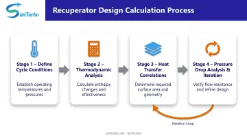
The recuperator design calculation process moves through four linked stages:
- Define cycle conditions: compressor discharge temperature and pressure, plus turbine exhaust temperature and pressure
- Run thermodynamic analysis to determine required effectiveness and heat duty
- Apply heat transfer correlations to calculate required surface area
- Finish with pressure drop analysis and iteration to optimize the design within constraints
Input Parameters
The process requires:
- Mass flow rate of exhaust gas
- Turbine exit temperature and pressure
- Compressor discharge temperature and pressure
- Target effectiveness or temperature approach
- Allowable pressure drops on hot and cold sides
- Material temperature limits
- Physical size and weight constraints for the application
From Thermodynamics to Geometry
Thermodynamic relationships (energy balance equations) combine with heat transfer correlations (Nusselt number relationships for the flow geometry) and pressure drop correlations (friction factor equations). Together they set the physical geometry (length, width, height, and passage dimensions) that meets performance and constraint requirements at the same time.
Engineers then iterate. They adjust surface area, flow passage dimensions, and flow velocities until calculated effectiveness, pressure drops, and heat transfer coefficients converge on the specification targets. Interdependent variables usually make computational tools or specialized software necessary.
SimTurbo's recuperator component automates this iteration inside integrated cycle simulations. Engineers can add recuperators to single-spool turbojet configurations, change parameters, and immediately see effects on cycle efficiency, pressure paths, and component matching. That feedback catches design errors early, before detailed calculations or hardware commitments.
Output Specifications
The calculation process turns general performance goals (such as improving cycle efficiency) into specific physical parameters:
- Recuperator dimensions (for example, 1.2 m × 0.8 m × 0.6 m)
- Heat transfer surface area (for example, 85 m²)
- Flow passage configuration (for example, 2 mm × 2 mm channels)
- Expected performance metrics (effectiveness = 88%, hot-side ΔP = 2.4%, cold-side ΔP = 2.1%)
Step 1: Calculate Heat Duty and Required Effectiveness
Start with an energy balance on the recuperator:
Q = ṁ_cold × cp × (T_cold_out - T_cold_in)
Where:
- Q = heat duty (W)
- ṁ_cold = cold-side mass flow rate (kg/s)
- cp = specific heat at constant pressure (J/kg·K)
- T_cold_out = compressor discharge air outlet temperature (K)
- T_cold_in = compressor discharge air inlet temperature (K)
Set the cold-side temperature rise from either your target cycle efficiency gain or the maximum allowable approach to turbine exhaust temperature.
With those temperatures defined, calculate effectiveness:
ε = (T_cold_out - T_cold_in) / (T_hot_in - T_cold_in)
Where:
- ε = effectiveness (dimensionless, 0 to 1)
- T_hot_in = turbine exhaust gas inlet temperature (K)
High-performance counterflow recuperators typically target 85–90% effectiveness. Some microturbine recuperator specifications call for greater than 90%.
Step 2: Determine Required Heat Transfer Area
Use the effectiveness-NTU method to turn the effectiveness from Step 1 into a required heat transfer surface area.
- Find NTU from effectiveness using the relationship for your flow arrangement
- Counterflow: NTU = -ln[1 - ε(1 - C_r)] / (1 - C_r), where C_r = C_min/C_max
- Solve for area: A = NTU × C_min / U
Where:
- A = heat transfer surface area (m²)
- C_min = minimum heat capacity rate = ṁ × cp (W/K)
- U = overall heat transfer coefficient (W/m²·K)
Estimate U from similar designs first, then verify it with detailed heat transfer analysis. Geometry, flow conditions, and surface enhancement drive the final value.
Step 3: Select Flow Configuration and Passage Geometry
Choose the recuperator type and flow arrangement based on your effectiveness target, packaging limits, and maintenance needs:
Recuperator Types:
- Primary surface (plate-fin): High surface area density, good for compactness
- Printed circuit: Very high effectiveness, tight passages, higher cost
- Tubular: More robust, easier to clean, lower effectiveness
Flow Arrangements:
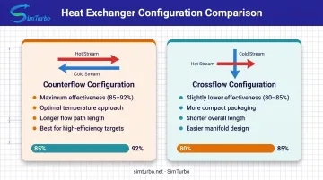
- Counterflow: Maximum effectiveness (use when ε > 85% is required)
- Crossflow: More compact packaging, slightly lower effectiveness
Passage geometry follows from those choices. Published microturbine recuperators use a 1.54 mm hydraulic diameter with surface area densities of 1,192-1,717 m²/m³. That sits well above 1,000 m²/m³ and shows why compact designs commonly use passage hydraulic diameters in the 1-3 mm range.
Step 4: Calculate Heat Transfer Coefficients and Validate Area
Perform detailed convective heat transfer analysis on both the hot and cold sides:
- Calculate Reynolds number: Re = ρ × V × D_h / μ
- Select appropriate correlation:
- Dittus-Boelter for fully developed turbulent flow
- Shah-London for developing flow
- Manufacturer data for enhanced surfaces
- Calculate heat transfer coefficient h on each side from the Nusselt number (h = Nu · k / D_h)
- Combine to get overall U: 1/U = 1/h_hot + t_wall/k_wall + 1/h_cold
- Verify calculated area against the requirement from Step 2
If the required area does not match, adjust passage dimensions and repeat. Geometry, velocity, h, and pressure drop are tightly coupled, so iteration—or a simulation tool that closes that loop—is part of the design process.
Step 5: Calculate Pressure Drop and Iterate Design
Calculate pressure drop on both hot and cold sides using:
ΔP = f × L × G² / (2 × ρ × D_h) + entrance/exit losses
Where:
- f = friction factor from Moody chart or correlations
- L = flow path length (m)
- G = mass flux (kg/s·m²)
- ρ = density (kg/m³)
- D_h = hydraulic diameter (m)
Express as relative pressure loss: ΔP/P_inlet (typically 2-3% maximum)
Verify that pressure drops stay within allowable limits. If they do not, adjust one or more of:
- Passage dimensions
- Recuperator length
- Frontal area
Then iterate the full design until effectiveness, size, and pressure-drop constraints are met together.

SimTurbo's component-based architecture lets engineers explore these trade-offs in real time. Connect a recuperator in the engine flow path and run transient simulations: you see pressure losses show up immediately in cycle performance, turbine work, and net efficiency. That feedback helps you avoid optimizing effectiveness while ignoring pressure penalties.
Step 6: Perform Off-Design and Thermal Stress Analysis
Validate the design at off-design conditions:
- Startup and shutdown transients
- Part-load operation
- Varying ambient temperature and altitude
Calculate thermal stresses from temperature gradients and thermal expansion mismatches. Verify structural integrity against low-cycle fatigue and creep.
The WR-21 program required 15,000 thermal cycles and 75,000 pressure cycles over 100,000 hours. That duty cycle shows transient loads and cyclic stresses often dominate recuperator life. Designs that look fine under steady conditions can still fail from thermal fatigue, so transient analysis belongs in the design loop—not as a late check.
Key Parameters That Affect Recuperator Performance
Recuperator performance is governed by the interaction of thermodynamic, heat transfer, and fluid dynamic parameters. Understanding which parameters have the strongest influence allows engineers to focus optimization efforts where they matter most.
Temperature Differential and Approach Temperature
The difference between turbine exhaust temperature and compressor discharge temperature determines the maximum possible heat recovery. Effectiveness is limited by the approach temperature required to achieve practical heat transfer area.
A microturbine study at pressure ratio 3-4 used hot/cold inlet temperatures of 975/576 K (399 K differential), enabling effectiveness targets of 75% and above. In contrast, high-pressure-ratio turbines may have compressor discharge temperatures approaching exhaust temperatures, leaving insufficient differential for effective heat recovery.
Pressure Ratio and Mass Flow Rate
The gas turbine's pressure ratio directly affects recuperator feasibility. Research indicates maximum recuperator benefit at pressure ratios not much above 8:1, with a typical optimum around 3-4 for microturbines.
High pressure ratios above this range shrink the temperature differential and make recuperation less effective.
Mass flow rate sets recuperator size for a given effectiveness: larger engines need proportionally larger heat transfer area. Flow imbalance between hot and cold sides—from combustor fuel addition and turbine cooling-air extraction—must be included in the calculations.
Heat Transfer Surface Area and Configuration
Increasing heat transfer area improves effectiveness but with diminishing returns. Moving from 80% to 85% effectiveness requires much less additional area than moving from 90% to 95%.
Surface configuration fundamentally affects heat transfer coefficient and pressure drop characteristics:
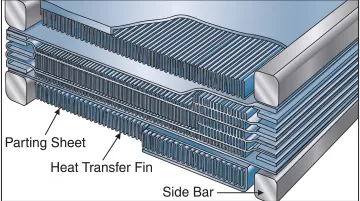
- Plate-fin recuperators: 1,192 m²/m³ area density documented
- Primary-surface designs: 1,299-1,717 m²/m³ area density
- Printed-circuit recuperators: Very high effectiveness in compact volumes
Each configuration offers different trade-offs between compactness, effectiveness, pressure drop, manufacturing cost, and fouling resistance.
Pressure Drop Allocation and Flow Velocity
Pressure drop scales with the square of velocity. Smaller passages raise surface area density but also raise pressure drop unless flow velocity is reduced. Lower velocity means larger frontal area and more recuperator weight.
The typical design target accepts 2-3% total pressure drop as aggressive but achievable before efficiency gains are negated. However, documented examples show wider ranges:
- Desired microturbine specification: <3% relative pressure loss
- WR-21 marine turbine: 5.9% hot-side, 5.1% cold-side at design point
- Helicopter study: 3-5% maximum allowable loss
Pressure drop limits are application-specific. Validate them with full cycle analysis before locking the design.
Material Properties and Temperature Limits
Material thermal conductivity affects conduction resistance through the separating wall, though this is usually negligible compared to convection resistance. Material temperature limits constrain maximum operating temperatures and durability.
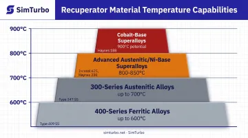
ORNL research on recuperator materials identifies temperature regimes:
- 400-series ferritic alloys: Up to 600°C
- 300-series austenitic alloys: Up to 700°C
- Advanced austenitic/Ni-base superalloys: 800-850°C development targets
- Cobalt-base superalloys: 900°C potential
Current metallic recuperators generally operate below about 650°C gas inlet temperature. Higher-temperature alloys support hotter turbine exhaust but cost significantly more.
Type 347 stainless steel is typical below about 650°C gas inlet. Inconel 625 and Haynes 230 are candidates for hotter service, though production limits for recuperator duty are less established.
Common Calculation Errors and Misconceptions
Three mistakes show up often in recuperator design calculations. Each one can erase the fuel savings the heat exchanger was meant to deliver.
Confusing Effectiveness with Efficiency
Effectiveness (ε) measures how close the recuperator comes to the thermodynamically ideal heat transfer between the two streams. Efficiency refers to the improvement in overall cycle thermal efficiency.
A recuperator can hit 90% effectiveness and still improve cycle efficiency by only a few percentage points. Engineers who mix up these metrics often over-specify effectiveness, taking on cost, weight, and pressure-drop penalties when a lower-effectiveness unit would deliver the same fuel savings.
Neglecting Pressure Drop Impacts
Many preliminary designs focus only on achieving target effectiveness without properly accounting for pressure drop, which directly reduces turbine work output. Pressure losses can eliminate 30-50% of the efficiency gain from heat recovery.
SimTurbo's integrated cycle simulation helps engineers catch this error early by showing net cycle performance with realistic pressure-drop models. With the recuperator in the flow path and pressure losses accounted for in real time, engineers see how effectiveness gains trade against pressure penalties before committing to hardware. That early check prevents costly redesigns.
Using Steady-State Analysis Only
Recuperators in gas turbine systems see transient thermal loads during startup, shutdown, and load changes. Those loads create thermal stresses that steady-state design calculations miss.
The WR-21 failure analysis revealed high thermal stress cracking and inadequate low-cycle-fatigue life predictions. Designs that look fine under steady conditions can still fail from thermal fatigue, so transient analysis is essential for reliable operation.
SimTurbo's transient simulation lets engineers model startup sequences, acceleration, and load changes. That check confirms recuperator designs can handle real operating cycles.
When Recuperators May Not Be Appropriate
High-Pressure-Ratio Limitations
Gas turbines with pressure ratios above approximately 8:1 have compressor discharge temperatures that approach turbine exhaust temperatures, leaving insufficient temperature differential for effective heat recovery. In these cases, the recuperator adds cost, weight, and pressure drop with minimal efficiency benefit, making the simple cycle more cost-effective.
Weight and Volume Constraints
Aerospace applications—especially UAVs and small aircraft—have strict weight and volume limits. A 300-kW helicopter turboshaft study illustrates the tradeoff. On a 39-km patrol mission, fuel savings of 9.36–13.02 kg could not offset recuperator mass additions of 38.2–277.2 kg across the studied designs—none paid back the mass penalty on that short profile.
Mission results varied by profile:
- Search-and-rescue: Tubular designs stayed beneficial through about 75% effectiveness; 80–90% primary-surface cases were unfavorable
- Offshore transport: Primary-surface benefit was positive at 80% effectiveness but negative at 85% and above
Engineers should run mission-level mass-minus-fuel analysis rather than assume recuperation always helps.
Maintenance and Reliability Concerns
Recuperators in contaminated exhaust—marine salt spray or industrial particulates—foul over time, which degrades performance and drives frequent cleaning.
ORNL reports additional durability risks on primary-surface units:
- Creep restricts hot-gas passages, cutting power and raising fuel use
- Oxidation/corrosion and fatigue cracks leak compressed air into the exhaust and lower efficiency
For applications where maintenance access is limited or where high reliability is critical, designers may choose to forgo recuperation despite efficiency benefits.
Cost-Effectiveness Boundaries
Recuperators add significant capital cost. ORNL data places recuperators at 25-30% of microturbine system cost. The fuel savings must justify this investment over the system lifetime.
For applications with low fuel costs, low operating hours, or short equipment lifetimes (e.g., emergency backup generators), recuperation is rarely economically justified. A DOE CHP case study assuming approximately 7,000 hours/year operation yielded 5.49 years simple payback—acceptable for industrial cogeneration but potentially unattractive for applications with lower utilization.
Conclusion
Recuperator design calculations apply thermodynamic and heat transfer principles to size a configuration that meets target effectiveness within pressure drop, temperature, weight, and cost limits. The process turns cycle-level requirements into geometric parameters—dimensions, passage sizes, and surface areas—through iterative trade-offs among competing objectives.
In gas turbine work, those gains hold only when effectiveness is balanced against pressure-drop penalties and the unit stays reliable under transient conditions.
Engineers who master the calculations and validate designs with integrated cycle simulation tools (including platforms such as SimTurbo) can deliver measurable efficiency gains in aerospace, marine, and distributed power applications—and avoid costly failures from oversimplified analysis.
Frequently Asked Questions
What is the difference between a regenerator and a recuperator?
Recuperators transfer heat through stationary surfaces between separate hot and cold streams that never mix. Regenerators use rotating or valve-switched thermal mass that alternately stores and releases heat. Gas turbines prefer recuperators to avoid sealing issues and moving parts.
How do you calculate recovery efficiency?
Recovery efficiency (effectiveness, ε) is ε = (T_cold_out - T_cold_in) / (T_hot_in - T_cold_in) on the cold side: actual heat recovered divided by the theoretical maximum. High-performance counterflow recuperators typically achieve 85-92% effectiveness.
What parameters have the strongest influence on recuperator effectiveness?
Surface area, overall heat transfer coefficient (U), and the heat capacity rate ratio (C_min/C_max) matter most. Effectiveness rises asymptotically as NTU = UA/C_min increases; doubling area helps most when effectiveness is still below about 70-80%.
How do you calculate pressure drop in a recuperator?
Calculate ΔP = (f × L/D_h × ρ × V²/2) plus entrance and exit losses, where friction factor f depends on Reynolds number and surface roughness. Express ΔP as a percentage of absolute pressure; relative loss is what reduces turbine work and cycle efficiency.
When is a recuperator cost-effective in a gas turbine cycle?
Recuperators pay off best in small-to-medium gas turbines at 3-8:1 pressure ratios with high annual hours, where fuel savings offset a 25-30% capital premium. Cost-effectiveness depends on mission profile, fuel prices, and equipment life, so analyze each application separately.