Introduction
Heat exchangers are central to energy-intensive work in aerospace, marine propulsion, power generation, and chemical processing. Engineers designing gas turbines, condensers, or refrigeration systems need accurate models to predict thermal performance, guide design decisions, and cut expensive physical prototyping.
The U.S. Department of Energy estimates that industrial processes use roughly 8,400 TBtu/yr, with approximately 1,478 TBtu/yr of waste heat above 77°F that could be recovered through heat exchangers. ASME also reports that computational modeling reduces the number of physical tests required during product development.
This article covers the fundamentals you need: classification systems that guide modeling strategy, the core physics behind energy and momentum balance, software approaches from analytical methods to CFD, and real-world applications across aerospace, marine, and HVAC systems.
Key Takeaways
- Heat exchanger modeling integrates thermal resistance networks with flow dynamics to predict duty and pressure loss
- Approach selection (analytical, 1D lumped, or CFD) depends on geometry complexity, design stage, and required spatial resolution
- Construction type and flow arrangement determine which correlations and effectiveness relations apply
- Validation against test data or manufacturer ratings is mandatory; sensitivity studies show which parameters govern accuracy
- Modern tools enable rapid iteration, but no single model serves every application; match fidelity to the decision at hand
Classification of Heat Exchangers
Classification tells you which modeling methods fit a design and how thermal behavior should be represented. Construction type and flow arrangement each impose different resistance networks, pressure-loss mechanisms, and correlation needs.
By Construction Type
Shell-and-Tube Exchangers
One fluid flows through a tube bundle; the other flows around the tubes inside the shell. These units dominate industrial service because they handle single-phase, boiling, and condensing duty.
Modeling typically requires:
- Separate shell- and tube-side convection correlations
- Baffles, leakage paths, and bypass streams
- Checks for potential tube vibration
Plate Heat Exchangers
Corrugated plates form alternating channels with high surface area in a compact footprint. Gasketed stacks can add or remove plates and support true counterflow.
Model inputs usually include:
- Channel hydraulic diameter and plate-pattern correlations
- Port and header distribution assumptions
- Gasket pressure and temperature limits
Double-Pipe (Concentric Tube) Exchangers
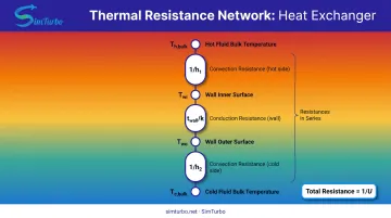
The simplest layout puts one pipe inside another. Inner convection, wall conduction, and outer convection sit in series. With fairly uniform flow and stable properties, closed-form LMTD or effectiveness-NTU analysis is often enough.
Finned-Tube Exchangers
Fins raise effective heat-transfer area, so these show up in air-cooled radiators, condensers, and recuperators. Include fin efficiency for the temperature drop along the fin; air-side resistance usually dominates the overall UA.
By Flow Arrangement
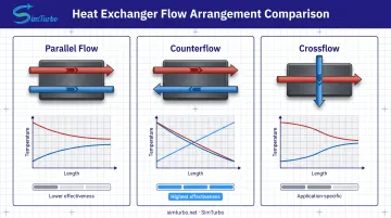
| Arrangement | Flow direction | What it means for modeling |
|---|---|---|
| Parallel flow | Same direction | Simpler equations; both streams approach a shared outlet limit, so effectiveness is lower |
| Counterflow | Opposite directions | Highest effectiveness and closest approach temperatures; common design baseline |
| Crossflow | Perpendicular | Common in air-cooled gear; mixed vs. unmixed streams set the F-correction or ε-NTU relation |
For crossflow, treat a stream as unmixed when it stays in separate channels and mixed when it can redistribute. That choice changes which correction factor or effectiveness relation you apply.
Fundamentals of Heat Exchanger Modeling
All heat exchanger models rest on a common principle: thermal energy transfers from a hot fluid to a cold fluid through a separating wall, without the fluids mixing. Useful models quantify both thermal resistance and fluid energy balances.
Thermal Resistance Concept
The overall heat transfer coefficient (U) combines convection resistances on both fluid sides plus conduction resistance through the wall:
1/U = 1/h₁ + t_wall/k + 1/h₂
For finned surfaces, add area-basis conversions and fin efficiency. For fouled surfaces, add fouling resistances explicitly.
The fundamental heat-transfer equation is:
Q = U × A × ΔT_LM
where Q is heat duty, A is surface area, and ΔT_LM is the log mean temperature difference. For multipass and crossflow configurations, apply the appropriate correction factor.
Energy Balance Equations
Energy conservation requires that heat lost by the hot fluid equals heat gained by the cold fluid (assuming negligible losses):
Q = ṁ_hot × cp_hot × (T_hot,in − T_hot,out) = ṁ_cold × cp_cold × (T_cold,out − T_cold,in)
You can calculate outlet temperatures if you know mass flow rates, specific heats, and heat duty. Any imbalance signals a modeling error or heat leak.
Key Dimensionless Numbers
Reynolds Number (Re)
Re = ρ V D_h / μ
Re characterizes flow regime (laminar or turbulent) and selects the appropriate friction and heat-transfer correlations. Thresholds depend on geometry, entrance effects, and disturbances.
Nusselt Number (Nu)
Nu = h D_h / k
Nu relates convective to conductive heat transfer. Once you have Nu from a validated correlation, you calculate the convection coefficient h.
Effectiveness-NTU Method
An alternative to LMTD when outlet temperatures are unknown:
- Effectiveness = Q / Q_max
- Q_max = C_min (T_hot,in − T_cold,in)
- NTU = UA / C_min
Effectiveness depends on NTU, capacity-rate ratio, and flow arrangement. This method is especially useful for sizing new exchangers or comparing design alternatives.
Common Correlations
- Dittus-Boelter: Nu = 0.023 Re^0.8 Pr^0.4 (turbulent flow, moderate property variation)
- Sieder-Tate: Nu = 0.027 Re^0.8 Pr^(1/3) (μ_bulk/μ_wall)^0.14 (accounts for bulk-to-wall viscosity changes)
Always verify that your operating conditions fall within the correlation's validated range.
Pressure Drop Considerations
Friction, flow acceleration, and geometry changes cause pressure losses that require pump or fan work, reducing overall system efficiency. Pressure-drop models must account for:
- Distributed friction (use friction factor correlations such as f = 64/Re for laminar flow)
- Entrance and exit losses
- Contractions, expansions, bends, and headers
- Baffle effects in shell-and-tube designs
- Acceleration and gravity terms
- Two-phase flow effects in evaporators and condensers
No single "typical" pressure-drop range applies universally; allowable loss is a system-level design constraint.
Modeling Approaches and Software Tools
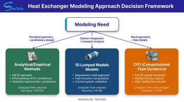
Choose a modeling approach based on design stage, required accuracy, compute budget, and available expertise. Match model fidelity to the decision you need to make—not to the most detailed tool on the shelf.
Analytical and Empirical Methods
Use simplified approaches with literature correlations (Dittus-Boelter, Sieder-Tate, and similar) for:
- Preliminary sizing and feasibility studies
- Standard geometries with well-documented performance
- Steady-state rating of existing equipment
Limitations: These methods assume idealized conditions, uniform flow, and negligible fouling. They often miss flow maldistribution and local hot spots.
1D/Lumped Parameter Models
Discretize the heat exchanger into segments along the flow direction and solve energy balances for each node.
Advantages:
- Computationally fast
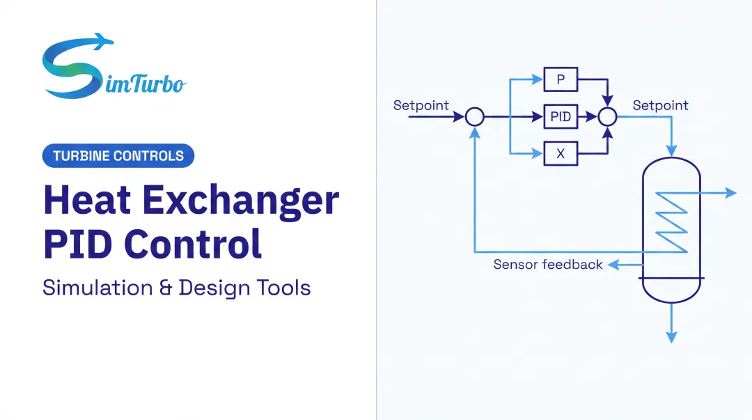
- Suitable for system-level simulation, transient analysis, and control design
- Can represent property variations along the flow path
Limitations: Lumped models can track overall warm-up trends seen in CFD, but they typically cannot resolve spatial temperature variation inside each segment.
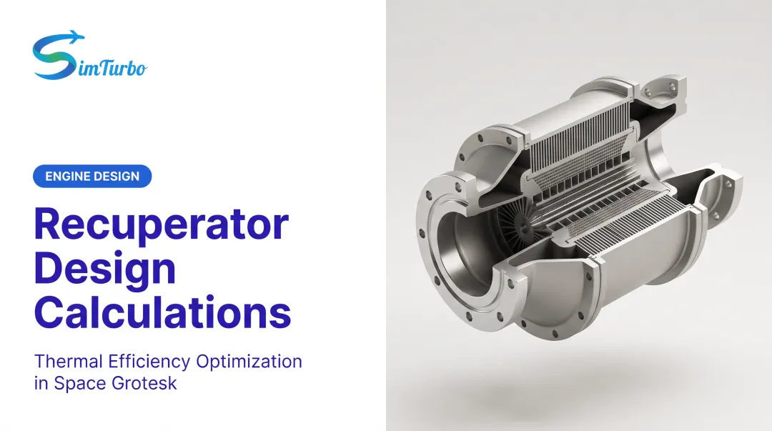
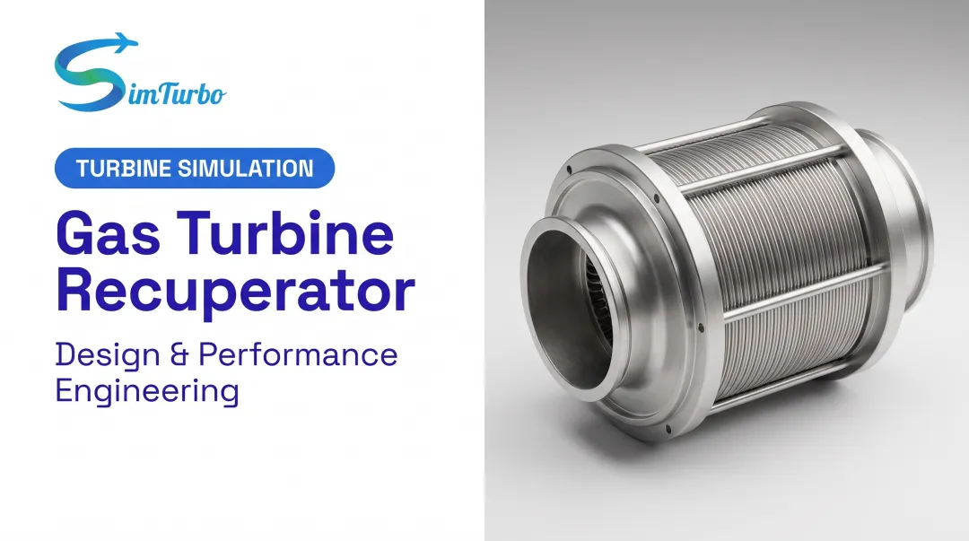
Example application: Recuperators in gas turbine cycles, where the exchanger couples to compressors, combustors, and turbines. In a tool such as SimTurbo, you place recuperators in a component-based engine model and run system-level and control studies without treating the core as a black box.
Computational Fluid Dynamics (CFD)
CFD solves the Navier-Stokes and energy equations on a detailed 3D mesh, capturing complex flow patterns, recirculation, conjugate heat transfer, and local temperature distributions.
When to Use CFD:
- Novel geometries without validated correlations
- Flow maldistribution concerns
- Detailed optimization of flow paths
- Validation of simplified models
Trade-offs: High fidelity comes at a cost. Industry CFD workflows (for example, multi-step condenser models that use pressure-jump approximations) often simplify geometry to keep run times workable. Even then, expect heavy setup time, careful meshing, and experienced users to reach trustworthy convergence.
Real-Time and Rapid Simulation Tools
Specialized platforms enable real-time or near-real-time simulation for iterative design and control validation:
- Rapid what-if analysis — explore design variations without overnight CFD runs
- Control system validation — test startup, shutdown, and transient response before hardware tests
- Education and training — visualize transients and parameter sensitivity interactively
SimTurbo is one example aimed at gas turbine work: real-time runs on a standard PC, live graphs and cycle diagrams, and drag-and-drop recuperators or intercoolers in the engine flow path. That setup supports cycle studies and control-law checks when full 3D CFD would slow the loop.
Industry Applications and Use Cases
Heat exchanger modeling requirements vary significantly by industry due to different fluids, operating conditions, and performance priorities.
Aerospace and Gas Turbine Systems
Recuperators recover exhaust heat to preheat compressor discharge air, improving thermal efficiency in gas turbines. A 1979 NASA study of turbine inlet temperatures from 816 to 1,093°C found efficiency improvements below 3% for specific steam-augmented recuperated configurations. Those gains depended strongly on evaporator pressure drop, recuperator effectiveness, compressor pressure ratio, and turbine staging.
Modeling Challenges:
- High temperatures requiring accurate material and property data
- Compact designs with tight packaging constraints
- Pressure-drop prediction critical to avoid cycle performance penalties
- Thermal stress and leakage paths that affect durability
Marine Propulsion and Power Generation
Marine heat exchangers cool engine systems using seawater, which raises corrosion and biofouling risk. A 2020 U.S. Navy study reported that flushing titanium seawater exchangers at 3 m/s removes most particulates, and testing envelopes extended to 38°C.
Models must account for biological, corrosion, crystallization, and particulate fouling. Rates depend on temperature, velocity, oxygen content, and upstream metallurgy.
Power generation adds different constraints. Steam condensers are critical for cycle efficiency. An ASME study validated CFD against full-scale plant tests and found that distorted inlet flow reduced upstream-fan performance, causing wind-related condenser degradation. CFD becomes essential when wind, fan interaction, or flow maldistribution governs performance.
HVAC and Refrigeration
Evaporators and condensers in refrigeration cycles must account for two-phase flow and refrigerant property variations. NIST's CYCLE_D-HX divides exchangers into superheated-vapor, two-phase, and subcooled-liquid regions. It supports counterflow, crossflow, and parallel flow with detailed property and pressure-drop treatment.
Part-load performance modeling is critical because HVAC systems operate at varied conditions throughout the year. Rather than a single full-load coefficient, models should track changing mass flow, phase-zone lengths, air and refrigerant distribution, fan and pump power, and control state.
Best Practices and Common Challenges
Successful modeling requires both theoretical understanding and practical engineering judgment. Follow these practices to ensure reliability and avoid common pitfalls.
Model Validation and Uncertainty
- Compare heat duty, outlet temperatures, and pressure drop to manufacturer ratings, experiments, or benchmarks at multiple operating points
- Vary U-values, flow distribution, fouling resistances, fluid properties, and ambient conditions to find high-influence parameters
- Treat fouling as site-specific; ASHRAE ties it to water quality, velocity, and tube geometry, so handbook factors need local validation
- Keep verification, validation, and uncertainty quantification separate (ASME: model math, real-world fit, and parameter variation)
Common Modeling Errors
Temperature Crossover in Counterflow
If the model predicts cold outlet temperature above hot outlet temperature, the result is physically impossible. Treat it as a specification or calculation error.
Improper Flow Distribution Assumptions
Assuming uniform flow when headers, baffles, or wind cause maldistribution underpredicts pressure drop and overpredicts heat transfer. Model distribution effects or validate the uniform-flow assumption experimentally.
Neglecting Entrance and Exit Effects
In short exchangers, developing flow regions occupy a significant fraction of total length. Fully developed correlations will overpredict performance; use entrance-region corrections or empirical adjustment factors.
Using Correlations Outside Their Range
Correlations are validated for specific Reynolds, Prandtl, and geometry ranges. Extrapolating beyond these limits introduces unknown error.
Iterative Design Process
- Start with analytical methods for initial sizing and feasibility
- Move to 1D segmented models for transient analysis, system integration, and sensitivity studies
- Reserve 3D CFD for novel geometries, suspected maldistribution, or cases where simplified assumptions hide the governing physics
- Weigh fabrication complexity, materials, maintenance access, and lifecycle cost alongside thermal-hydraulic performance

Frequently Asked Questions
How can I model heat exchangers?
Define fluids, flow rates, inlet temperatures, pressure drop, and duty, then pick construction type and flow arrangement. For preliminary work, use energy balances with LMTD or effectiveness-NTU and literature correlations; validate against manufacturer or test data. Escalate to segmented 1D models or CFD when geometry or uncertainty demands it.
What are the four types of heat exchangers?
The four main construction types are shell-and-tube, plate, double-pipe, and finned-tube. You can also classify by flow arrangement (parallel, counterflow, crossflow) or by application (condenser, evaporator, recuperator).
What is the difference between LMTD and effectiveness-NTU methods?
LMTD needs known or iterated inlet and outlet temperatures and suits rating existing exchangers. Effectiveness-NTU is better when outlets are unknown, such as sizing new units or comparing designs. Both use the same energy balance and overall conductance (UA).
How accurate are heat exchanger models compared to actual performance?
Accuracy depends on geometry, fluid properties, flow regime, fouling, distribution, and how well the model is validated. Validated models for standard configurations often match thermal duty within a few percent; pressure drop is usually less accurate. Uncertainty rises with fouling, off-design operation, and novel geometries.
What software is commonly used for heat exchanger modeling?
Industrial design often uses HTRI Xchanger Suite or Aspen Exchanger Design & Rating. CFD tools such as ANSYS Fluent and COMSOL handle complex geometry and conjugate heat transfer. System platforms like MATLAB/Simulink and SimTurbo support cycle-level studies, including recuperators in gas turbine models.
When should I use CFD versus simplified models for heat exchanger analysis?
Use analytical or 1D models for preliminary design, standard geometries, system studies, and fast iteration. Turn to CFD for novel geometries, suspected maldistribution, detailed optimization, or when you need high confidence without test data.