Unlike rocket engines that must carry both fuel and oxidizer, airbreathing engines draw oxygen directly from the atmosphere—dramatically reducing weight and enabling practical, efficient flight. This article explains how these systems work, the major engine types, and how simulation tools help engineers design, test, and optimize propulsion systems before physical prototypes leave the ground.
Key Takeaways:
- Airbreathing engines draw oxygen from the atmosphere rather than carrying oxidizer onboard, reducing weight and enabling efficient sustained flight
- Five main types serve different speed regimes: turbojets, turbofans, turboprops, ramjets, and scramjets
- Modern high-bypass turbofans achieve pressure ratios up to 60:1 and bypass ratios around 10:1 for maximum fuel efficiency
- Simulation platforms enable engineers to model thermodynamic cycles, validate control systems, and optimize designs before expensive physical testing
- Experimental scramjet vehicles have demonstrated speeds up to Mach 9.6 in research flights
What Is Airbreathing Propulsion?
Airbreathing propulsion refers to engines that use atmospheric air as the oxidizer for combustion. Instead of carrying heavy oxidizer tanks like rocket engines, these systems compress incoming air, mix it with fuel, ignite the mixture, and expel hot exhaust gases at high velocity to produce thrust.
The fundamental advantage is weight savings. By relying on atmospheric oxygen, airbreathing engines eliminate the need to carry oxidizer, making sustained flight practical for everything from regional turboprops to supersonic interceptors.
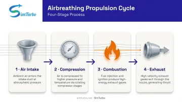
The basic operational cycle includes four stages:
- Air intake – Atmospheric air enters the engine
- Compression – Air pressure and temperature increase
- Combustion – Fuel burns in compressed air, releasing energy
- Exhaust – Hot gases accelerate through a nozzle, producing thrust
Airbreathing vs. Rocket Propulsion
The key difference lies in the oxidizer source. Rockets carry both fuel and oxidizer, enabling operation in space but at the cost of significant mass. Airbreathing engines only function where atmospheric oxygen is available (typically below 50,000–60,000 feet for conventional turbojets), but offer far better efficiency within that envelope.
This fundamental trade-off explains why airbreathing propulsion dominates subsonic and supersonic aviation, while rockets remain essential for space launch and exoatmospheric flight.
How Airbreathing Engines Work
Most airbreathing engines operate on the Brayton thermodynamic cycle, a sequence of compression, heat addition, expansion, and exhaust that converts fuel energy into propulsive force.
The Four Stages in Detail
- Intake/Compression: Air enters the engine and passes through a compressor, which raises pressure and temperature. Modern high-performance engines like the GE9X achieve overall pressure ratios around 60:1, while the GE90 variants reach 40:1 to 42:1.
- Combustion: Compressed air enters the combustion chamber, where fuel injectors spray atomized fuel. The mixture ignites and burns at approximately constant pressure, raising gas temperature.
- Expansion: Hot, high-pressure gases flow through turbine stages, which extract energy to drive the compressor and fan. The remaining energy accelerates the exhaust.
- Exhaust: Gases exit through a nozzle, converting thermal energy into kinetic energy and producing thrust.
How Thrust Is Generated
Thrust follows Newton's third law: accelerating air rearward produces an equal and opposite forward force. The relationship between thrust, air mass flow, and exhaust velocity is direct: more airflow or higher exhaust velocity means more thrust.
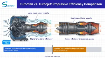
High-bypass turbofans improve efficiency by accelerating a large mass of air by a smaller amount, rather than accelerating a small mass to very high velocity. That yields higher propulsive efficiency, lower fuel burn, and less noise, which is why turbofans dominate commercial aviation.
Types of Airbreathing Engines
Different engine architectures serve distinct speed ranges and mission profiles—which is why commercial jets, fighter aircraft, and experimental hypersonic vehicles rely on fundamentally different propulsion systems.
Turbojet Engines
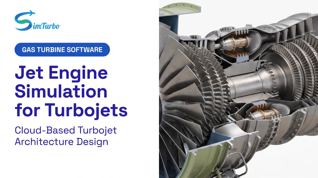
Turbojets compress air through rotating compressor stages, burn fuel in a combustion chamber, extract energy via a turbine that drives the compressor, and expel exhaust through a nozzle. All incoming air passes through the core, resulting in high exhaust velocity and lower propulsive efficiency at subsonic speeds.
Typical applications:
- Early jet aircraft
- High-speed military fighters that favor top speed over efficiency
- Legacy platforms such as the F-4 Phantom (GE J79)
Turbojets have largely been replaced by turbofans in most roles due to better fuel efficiency and quieter operation.
Turbofan Engines
Turbofans add a large fan at the front of the engine. Some air bypasses the core entirely, flowing around the combustion section and mixing with exhaust downstream. The bypass ratio—the ratio of bypass air to core air—defines the engine's character.
Key advantages:
- High-bypass designs (around 10:1 for the GE9X) deliver excellent fuel economy
- Lower exhaust velocity reduces noise by up to 75% compared to earlier engines
- Geared fans (e.g., Pratt & Whitney's GTF) claim up to 20% trip fuel savings on A320neo-family aircraft
The CFM56 family, with nearly 30,000 engines delivered and over 800 million flight hours logged by 2016, shows how far high-bypass turbofans have scaled in airline service. The GE90, powering Boeing 777 variants, has seen over 2,800 deliveries.
Ramjet and Scramjet Engines
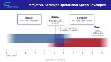
Ramjets eliminate rotating machinery entirely. Forward speed compresses incoming air through carefully shaped inlet shocks. Fuel burns in the compressed airflow, and exhaust exits through a nozzle. NASA research indicates ramjets operate effectively from approximately Mach 3 to Mach 6, though efficiency drops sharply above Mach 5 due to inlet-shock losses.
Limitations:
- Cannot produce static thrust—requires another propulsion system for initial acceleration
- Unsuitable for low-speed flight
Scramjets (supersonic combustion ramjets) extend the speed range by maintaining supersonic airflow through the combustion chamber, avoiding the losses from decelerating all inlet flow to subsonic speed. This design targets hypersonic atmospheric flight.
Demonstrated performance:
- NASA's X-43A reached Mach 9.6 on November 16, 2004
- The USAF X-51A Waverider achieved Mach 5.1 on May 1, 2013, covering over 230 nautical miles in just over six minutes
These remain experimental technologies, with programs like DARPA's MOHAWC continuing to mature scramjet operating envelopes.
Turboprop Engines
Turboprops use a gas-turbine core to drive a geared propeller. Most thrust comes from the propeller, not the jet exhaust. NASA notes that turboprops deliver better propulsive efficiency than turbojets below approximately 500 mph.
Applications:
- Regional aircraft and commuter planes
- Cargo aircraft requiring short-field performance
- Military transports
Propeller efficiency declines as speed increases, limiting turboprops to lower-speed missions where their fuel economy shines.
Key Components of Airbreathing Propulsion Systems
Understanding individual engine components helps engineers optimize performance, manage thermal loads, and design effective control systems.
Cold Section Components
Air Inlet:
The inlet shapes airflow for efficient compression. On supersonic aircraft, inlet shocks pre-compress air before it reaches the compressor.
Compressor Stages:
- Axial compressors: Airflow remains parallel to the shaft; multistage designs multiply pressure row by row. Large turbojets and turbofans typically use axial designs for higher pressure ratios
- Centrifugal compressors: Airflow turns perpendicular to the shaft; common in small engines
Hot Section Components
Combustion Chamber:
NASA identifies three main configurations: annular, can/tubular, and can-annular. Perforated liners promote fuel-air mixing and stabilize combustion.
Turbine Stages:
Turbines extract energy from hot gases to drive the compressor and fan.
Modern materials like ceramic matrix composites (CMCs) target operating temperatures of 1,482-1,648°C, over 100°C above single-crystal nickel superalloys. Silicon-carbide CMCs can withstand at least 1,315°C while offering lower thermal conductivity.
Hot-section durability issues include:
- Coating erosion under thermal and mechanical load
- Environmental-barrier coating cracking
- Oxide-silicate creep in high-temperature environments
Exhaust System
Nozzle Design:
- Fixed convergent nozzles: Common on simple turbojets and turboprops
- Variable convergent-divergent nozzles: Required for afterburning engines
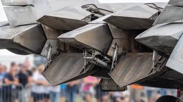
- Thrust vectoring: Rectangular exits can direct exhaust for enhanced maneuverability
The F-22 Raptor uses two F119-PW-100 afterburning turbofans with two-dimensional thrust-vectoring nozzles, enabling extreme agility.
Applications and Industries
Airbreathing propulsion systems form the backbone of global aviation, from daily airline operations to demanding military missions.
Commercial Aviation
Turbofans dominate commercial flight due to their strong fuel efficiency and noise performance. IATA's June 2025 report counted 35,550 total commercial aircraft, including 30,300 active aircraft and 5,250 stored. The industry forecasts consuming 106 billion gallons of fuel in 2026, up 2.7% from 103 billion gallons in 2025.
Leading engines:
- CFM56 family: First high-bypass turbofan to exceed 800 million flight hours
- GE90: Powers Boeing 777 variants, 2,800+ deliveries
- Pratt & Whitney GTF: Delivers up to 20% trip fuel savings and 75% smaller noise footprint on A320neo-family aircraft
Military Aviation
Fighter jets, bombers, and reconnaissance aircraft require propulsion systems optimized for high speed, rapid throttle response, and operational flexibility.
Examples:
- F-16 Fighting Falcon: One F100-PW-200/220/229 or F110-GE-100/129 turbofan, Mach 2 capability
- F-35A Lightning II: One F135-PW-100 turbofan, 43,000 pounds thrust, Mach 1.6 max speed
- B-2 Spirit bomber: Four F118-GE-100 turbofans, 17,300 pounds thrust each
Mission profiles still push engines toward sustained high-altitude operation, afterburner use for rapid acceleration, and tight control over wide flight envelopes.
Emerging Applications
- Hypersonic research: NASA and DARPA continue scramjet work for hypersonic flight. X-43A and X-51A proved the concept; operational aircraft are still in development.
- Air-breathing space launch: Turbine-based combined cycles that blend turbine and ramjet/scramjet modes have been studied for space access, but remain research concepts rather than fielded systems.
Design and Simulation Considerations
Designing airbreathing propulsion systems requires balancing thermodynamics, fluid dynamics, materials science, and control engineering. Physical testing remains expensive and time-consuming, so simulation tools are essential for modern development.
Engineering Challenges
Several constraints dominate early design work:
- Thermal management — Keep turbine-inlet temperatures inside material limits in steady running and during transients such as slam accelerations and afterburner ignition, using cooling schemes, thermal barrier coatings, and CMCs.
- Material selection — Higher overall pressure ratios and turbine inlet temperatures need alloys and coatings that resist creep, oxidation, and degradation under combined thermal and mechanical stress.
- Flight-envelope optimization — Deliver usable thrust and efficiency across altitude, Mach, and ambient temperature. Compressor and turbine maps set the operating points; off-design analysis confirms performance across the envelope.
The Role of Simulation
Simulation lets teams stress those thermal, materials, and envelope limits before metal is cut. Modern platforms model gas turbine performance across operating conditions without a physical prototype for every iteration, folding thermodynamics, component maps, real-gas effects, pressure losses, and control-system behavior into real-time models.
Key capabilities:
- Steady-state cycle analysis for design-point performance
- Transient simulation for startup, throttle changes, and fault conditions
- Component matching to optimize compressor and turbine interaction
- Control-law validation before hardware testing
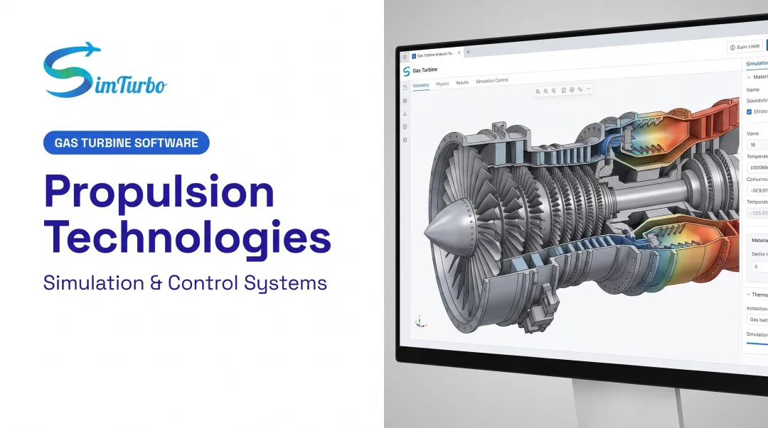
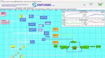
Platforms such as SimTurbo give aerospace engineers and students a graphical, component-based way to build engines from inlets, compressors, combustors, turbines, nozzles, and controls, run real-time simulations, and export results to Excel, MATLAB, or Python. SimTurbo’s J85-GE-21 single-spool turbojet model matched NASA Lewis Research Center test data within ±2% for thrust, flow rate, temperature, and thrust-specific fuel consumption.
Results still need to land in a form the industry trusts. SAE AS681L guides how computer programs present gas-turbine performance, and ASME PTC 55 covers aircraft-engine performance testing.
Virtual validation cuts rig-test cost, shortens design loops, and lets teams compare more cycle and control options before the first hardware build.
Frequently Asked Questions
What is airbreathing propulsion?
Airbreathing propulsion systems use atmospheric oxygen for combustion, distinguishing them from rocket engines that carry oxidizer onboard. This approach reduces weight, enabling efficient sustained flight within the atmosphere.
What are the different types of airbreathing engines?
The five main types are turbojets, turbofans, turboprops, ramjets, and scramjets. Turbojets and turbofans power most aircraft; turboprops excel below about 500 mph; ramjets suit Mach 3–6; scramjets handle hypersonic flight above Mach 5.
How do turbofan engines differ from turbojets?
Turbofans add bypass airflow around the engine core, with thrust generated by both the core jet and the bypass stream. Even low-bypass turbofans are more fuel-efficient than basic turbojets, while high-bypass designs deliver better fuel economy and lower noise.
Can a ramjet start from rest?
No. Ramjets require forward speed to generate compression and cannot produce static thrust. They need another propulsion system—such as a rocket booster or conventional turbojet—to accelerate the vehicle to operating speed.
Why are turboprops used at lower speeds?
Turboprop propellers move a large mass of air efficiently, delivering excellent fuel economy. However, propeller efficiency declines as aircraft speed rises, limiting turboprops to missions below approximately 500 mph where their advantages outweigh the speed penalty.
What is the Brayton cycle?
The Brayton cycle is the thermodynamic process governing most airbreathing engines: air is compressed, heat is added at approximately constant pressure, the hot gas expands through a turbine, and exhaust exits through a nozzle. This cycle converts fuel energy into propulsive thrust.