Many plants still struggle with this balance. Aging mechanical governors respond slower than digital alternatives. A sudden loss of electrical load can send a rotor toward dangerous overspeed in seconds. And grid frequency mismatches during synchronization can trip protective relays before a unit ever connects.
This article covers how governors function, how they control speed during startup and operation, the layered protection that prevents catastrophic overspeed, why turbines lock into fixed speeds like 3,600 RPM, and how modern simulation tools let engineers validate control logic before touching real hardware.
Key Takeaways
- Governors sense shaft speed and modulate steam valves to hold RPM steady under changing load
- US grid frequency (60 Hz) fixes two-pole generator speed at 3,600 RPM
- Overspeed protection uses independent, redundant trip layers separate from normal governing
- Simulation platforms let engineers validate control logic before hardware commitment
What Is the Function of a Steam Turbine Speed Governing System?
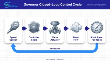
A steam turbine governor senses shaft speed, compares it to a target, and adjusts steam admission valves to close the gap. That single comparison-and-correct loop is the core job. The mechanism behind it, however, is a full closed loop:
Speed sensor → controller logic → valve actuator → steam flow → shaft speed feedback
Woodward's hydraulic-mechanical governors represent the older approach to this loop, while GE Vernova's Mark VIe platform runs the same function digitally, using triple-modular-redundant architecture for both control and protection. Two common implementations:
- Mechanical/hydraulic governors use flyball or hydraulic feedback; durable, but slower to reconfigure
- Digital/electronic governors use configurable software logic for faster tuning and clearer diagnostics
A governor's duties extend well beyond simple speed-holding:
- Startup speed ramping
- Load control after synchronization
- Overspeed trip protection
- Extraction or admission regulation for process steam (on some units)
Speed Sensing Methods
Everything in that loop starts with a clean speed signal. Most systems use a toothed or pole wheel passing a proximity probe. The probe reads tooth-to-notch timing, and that timing becomes the rotational speed input to the governor—a simple, rugged method proven over decades in industrial turbine service.
How Is Turbine Speed Controlled?
Turbine governing shifts modes depending on where the unit sits in its operating cycle.
During startup, the governor runs in speed-controller mode. It ramps the rotor through warm-up plateaus, then accelerates through critical-speed bands quickly rather than dwelling there. Lingering at a rotor's resonant frequency risks vibration damage, so the ramp profile is engineered to pass through, not sit in, those zones.
Once the unit reaches rated or synchronous speed, control transitions to a Speed/Load Controller. From here, the operating mode depends on grid connection status.
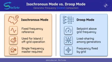
Isochronous Mode
Used for island or off-grid operation, isochronous control holds one fixed frequency reference. As load changes, the governor adjusts valve position to keep frequency constant. This mode works when a single unit is the frequency "master" for its island. Multiple isochronous governors on the same island will fight each other.
Droop Mode
Once synchronized to the grid, the turbine's speed setpoint is nudged slightly above grid frequency to share load with other generators. The governor cannot alter grid frequency directly. On a large interconnected grid, frequency is essentially fixed by the collective behavior of thousands of generators.
Droop determines how much MW a given unit contributes, not the frequency itself. NERC's steam-generation guidance frames this as an outer control loop using flow-demand bias or speed error, converted proportionally into load response.
Automatic Mode Transfer
If the grid tie breaker opens unexpectedly, a properly configured controller transfers instantly from droop to isochronous mode, driving the turbine toward rated no-load speed rather than letting it run away. This transfer logic is unit-specific and lives in the OEM's control diagrams — commissioning engineers verify it rather than assuming a generic sequence applies.
What Causes Turbine Overspeed and How Is It Prevented?
Destructive overspeed events don't happen from a single failure. They require three things to fail simultaneously: loss of load, failure of normal control, and failure of the overspeed protection system itself, according to Turbomachinery International's analysis of overspeed testing.
Common overspeed triggers include:
- Sudden loss of electrical load (generator breaker trip)
- Valve or actuator failure that prevents steam cutoff
- Governor malfunction or logic fault
- Water induction into the steam path
Layered Protection Architecture
No single safety layer is trusted alone. The design philosophy stacks independent barriers:
| Layer | Function |
|---|---|
| Governor | Normal control; limits steam and catches load rejection |
| Independent trip system | Closes stop/trip valves on overspeed, separate from normal control logic |
| Valve and testing program | Verifies the final mechanical element still works |
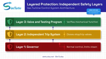
Woodward offers stand-alone, safety-certified overspeed protection in simplex or triple-redundant (TMR) configurations, deliberately isolated from the governor's normal control path. If the governor's logic fails, the trip system still has to work.
Emerson's guidance states the objective is keeping response below 120% of rated speed — a response ceiling, not a universal trip setpoint. Exact trip values are machine-specific and set by the OEM, not by a generic industry number.
A real consequence of failed layers: In May 2021, the Russell City Energy Center experienced a steam-turbine-generator event triggered by water induction, which led to overspeed, fire, and explosion. Lube oil fed the fire, and roughly 600 MW of generation was lost.
The CPUC's investigation found gaps in water-induction protection, alarm response, training, and critical-valve maintenance. The lesson: protection isn't only electronic. Steam-path drainage and valve health matter just as much as the trip logic itself.
Even sound protection layers need proof they still work—and that proof has risk of its own. Turbomachinery International notes that a significant share of overspeed incidents happen during testing, since removing load to test protection can itself destabilize normal control. Periodic testing remains necessary, but it needs careful procedure and often independent verification.
Why Do Steam Turbines Run at Fixed Speeds Like 3,600 or 3,000 RPM?
Once synchronized, a turbine-generator's speed is locked to the grid by a simple relationship:
Ns = 120 × f / P
Where Ns is speed in RPM, f is grid frequency in hertz, and P is the number of generator poles.
For a two-pole generator on the US grid (60 Hz):
120 × 60 / 2 = 3,600 RPM
For 50 Hz regions (much of Europe and Asia), the same math yields 3,000 RPM. Mitsubishi Power confirms these exact figures for its steam turbine line.
That relationship isn't universal:
- Four-pole 60 Hz generators run at 1,800 RPM
- Geared industrial units can spin the turbine shaft at a different speed than the generator, as long as the gearbox output stays synchronous
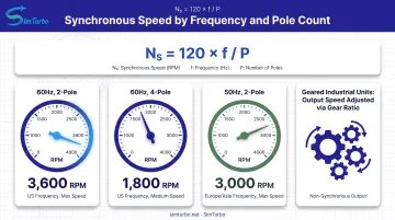
Once the breaker closes, the grid's electrical frequency and the generator's pole count fix the speed. The governor's role then shifts entirely to adjusting torque and power output, not RPM itself.
Simulating and Validating Speed Control Logic Before Deployment
Tuning a governor used to mean testing on real hardware, with real risk. Today, engineers validate speed-control logic in simulation before it ever touches a physical turbine.
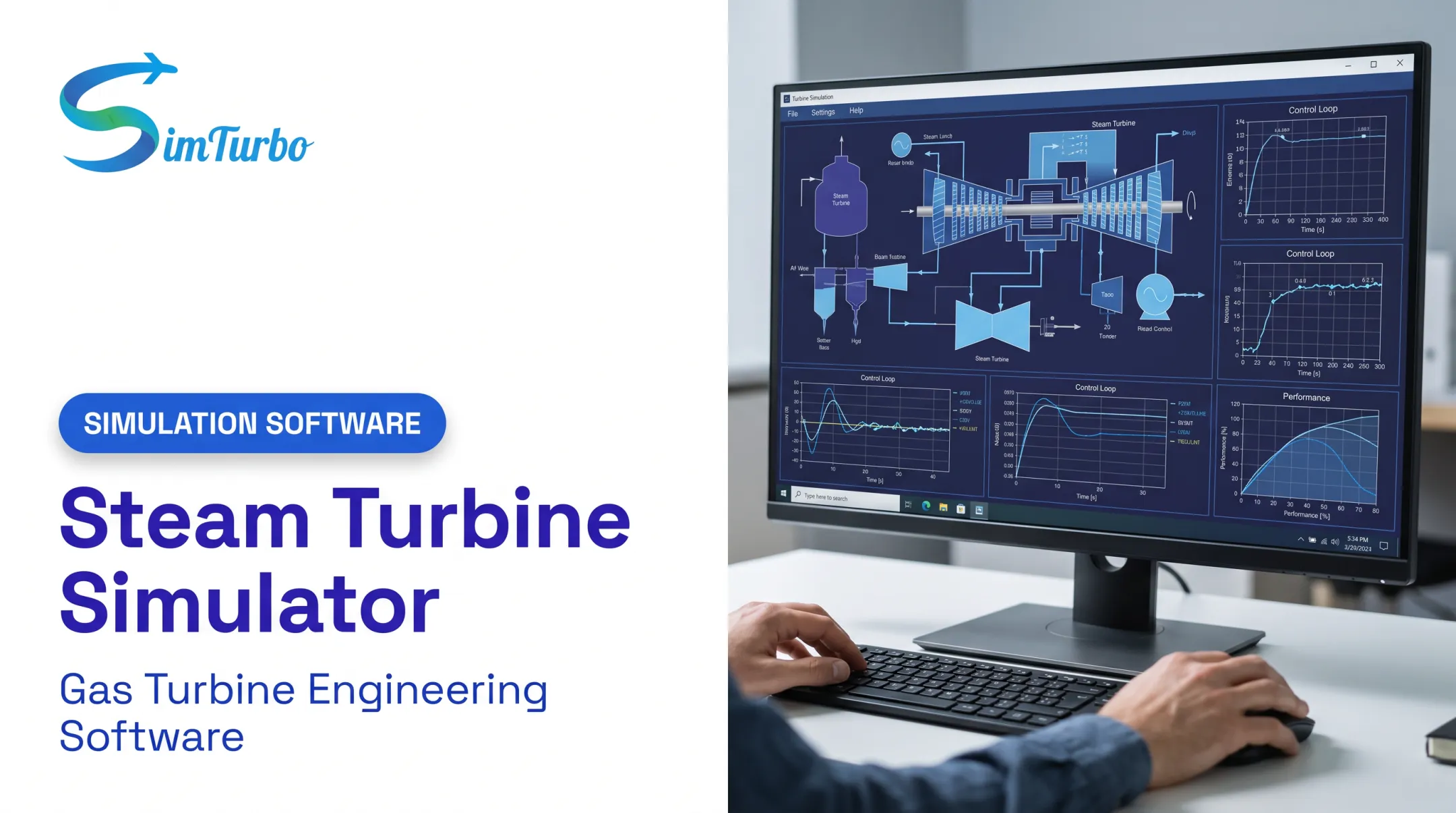
Simulation platforms let you model PID-based speed and load controllers, run transient scenarios, and watch valve-to-speed feedback on screen in real time, with no spinning rotor required. The same workflow (closed-loop speed control, setpoint steps, load changes, and fault cases) is how governor logic gets proven before deployment.
SimTurbo, from Controls Research LLC, is a gas-turbine example of that approach: a component-based, real-time environment where engineers assemble control logic from interconnected blocks:
- Speed PID controllers for RPM regulation
- Temperature PID and Surge Margin PID elements for related protection logic
- Actuators, sensors, limiters, signals, and sources for full control architectures
Engineers can run startup sequences, acceleration and deceleration events, load changes, and fault scenarios, then export transient results (RPM, EGT, thrust, SFC, and related channels) to Excel or CSV for post-processing.
The platform also supports external control-law checks by exporting plant-response data into MATLAB/Simulink or Python workflows. SimTurbo's core engine model has been validated against NASA Lewis Research Center J85-GE-21 test data, with reported accuracy within ±2% across thrust, flow rate, temperature, and fuel consumption. That figure applies to the engine simulation itself, not to a specific governor trip setpoint or control-law accuracy claim.
For capstone teams and control-system students, this kind of environment removes the need for dedicated turbine hardware just to learn governing principles. Teams can build closed-loop speed control, watch setpoint changes move valve position and shaft speed, and export the traces for analysis. That is the same fundamental exercise an OEM engineer runs before committing logic to a physical unit.
Frequently Asked Questions
What is the function of the speed governing system in a turbine?
The governing system senses shaft speed continuously and adjusts steam valve position to hold RPM at target, compensating automatically as load conditions change.
How is turbine speed controlled?
Startup uses ramp control through critical-speed bands, then transitions to either isochronous (frequency-holding) or droop (load-sharing) control depending on grid connection.
What causes turbine overspeed?
Primary causes include sudden loss of electrical load, generator breaker trips, valve or actuator failure, and governor malfunction. Overspeed usually requires multiple simultaneous failures.
Why do turbines run at specific speeds like 3,600 or 3,000 RPM?
These speeds come from the synchronous speed formula (Ns = 120f/P), tying generator speed directly to grid frequency and pole count.
What is pitch control and yaw control?
These are wind turbine terms (blade angle and nacelle orientation), not steam turbine concepts. Steam turbines regulate speed through valve position, not aerodynamic adjustment.
How accurate must speed control be during synchronizing to the grid?
Very tight. IEEE guidance suggests a typical closing-angle tolerance of about ±10 electrical degrees, though exact limits depend on breaker duty, generator design, and utility interconnection rules.