Key Takeaways
- Compressor blades raise pressure through diffusion stages; turbine blades extract work from hot exhaust
- Chord, twist, stagger, and camber set pressure distribution, flow turning, and efficiency
- Nickel superalloys handle HPT heat; titanium fits cool compressors; CMCs cut weight
- Simulation proves aero and structural limits before hardware, cutting time and cost
Fundamentals of Gas Turbine Blade Design
Aerodynamic and Thermodynamic Roles
Compressor blades accelerate and diffuse incoming air across multiple stages, raising static pressure and preparing it for combustion. In contrast, turbine blades extract kinetic energy from hot combustion gases, converting it into shaft work that drives the compressor and produces thrust or power.
According to MIT's unified propulsion course, stators add swirl and convert internal energy into kinetic energy, while turbine rotors remove that kinetic energy as mechanical work.
Engineers design each blade row with local velocity triangles that account for absolute flow in stators and relative flow in rotating stages. Pressure distributions across the blade surface determine how efficiently the flow turns and diffuses without separating. Excessive suction-side diffusion or incorrect incidence angle can trigger boundary-layer separation, raising total-pressure loss and reducing stage efficiency.
Geometry-to-Performance Relationships
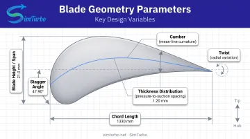
Key geometric parameters:
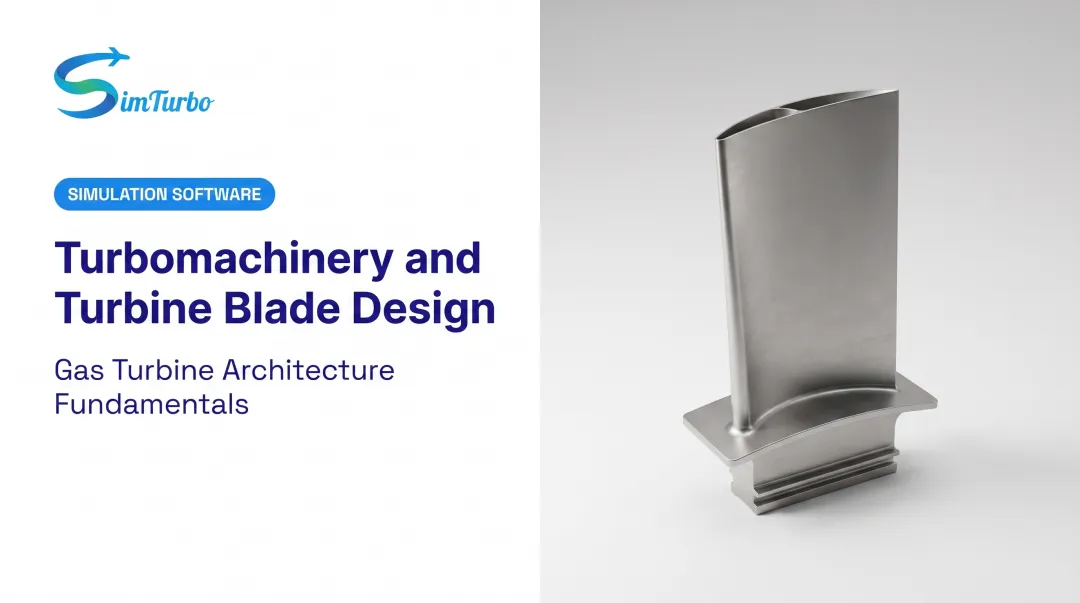
- Chord length — influences Reynolds number, surface diffusion, and structural section depth
- Blade height (span) — sets annulus area and aspect ratio; taller blades reduce endwall-loss fraction but increase vibration sensitivity
- Stagger angle — orients the chord line relative to the axial direction, controlling throat area and flow capacity
- Camber — curvature of the mean line; higher camber increases turning but raises separation risk under off-design conditions
- Twist — radial variation in metal angle; compensates for changing blade speed (U = ω × r) from hub to tip, matching local velocity triangles
The GE9X turbofan, for example, uses 3 booster stages, 11 high-pressure-compressor stages, 2 HPT stages, and 6 LPT stages to achieve a 60:1 overall pressure ratio and 27:1 core ratio.
Each stage geometry reflects its position in the compression or expansion path. Front compressor rows handle transonic inlet flow and need shock control, while turbine blades must endure extreme thermal loads and extract maximum energy.
Engine Efficiency and Fuel Consumption
Blade design affects overall cycle efficiency by controlling pressure rise per stage, temperature distribution, and aerodynamic losses. Efficient compression minimizes entropy generation, allowing higher combustion temperatures without exceeding turbine material limits.
Effective turbine-blade cooling permits inlet temperatures above 1,600°C, improving thermodynamic efficiency while preventing creep failure.
A 2017 NASA centrifugal-compressor test measured a 4.68 pressure ratio, 85.5% polytropic efficiency, 0.81 work factor, and 7.5% stall margin. Those results show how tightly real-world blade performance tracks geometry, materials, and operating conditions.
Types of Turbine Blades
Compressor Blades
Axial compressor blades:
- Airfoil profiles optimized for progressive pressure rise across 5–15 stages
- Operate at relatively cooler temperatures (300–700°C in later stages)
- Front stages face transonic inlet flow; passage shocks interact with suction-side boundary layers, raising unsteadiness and loss
- Titanium alloys such as Ti-6Al-4V dominate cooler sections; density near 60% of steel reduces centrifugal load
- Nickel-base materials appear in hotter rear stages where titanium oxidation becomes unacceptable above 600°C
Centrifugal impellers:
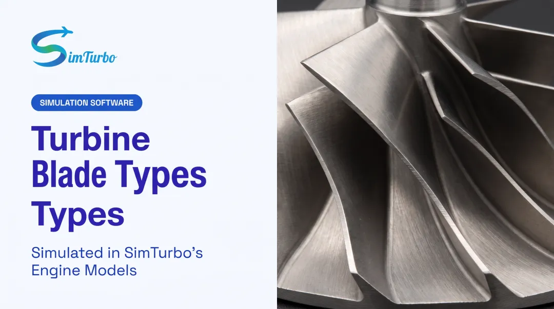
- Radial flow path turns incoming axial flow 90° outward, adding work through centrifugal acceleration
- High rotational speeds (often 30,000–50,000 RPM in small engines)
- Diffuser downstream converts kinetic energy into static pressure
- Compact, high-pressure-ratio capability (3–6:1 per stage) suits auxiliary power units and small turboshaft engines
Turbine Blades
High-pressure turbine (HPT):
- Extracts maximum energy from the hottest gas stream (1,400–1,700°C inlet)
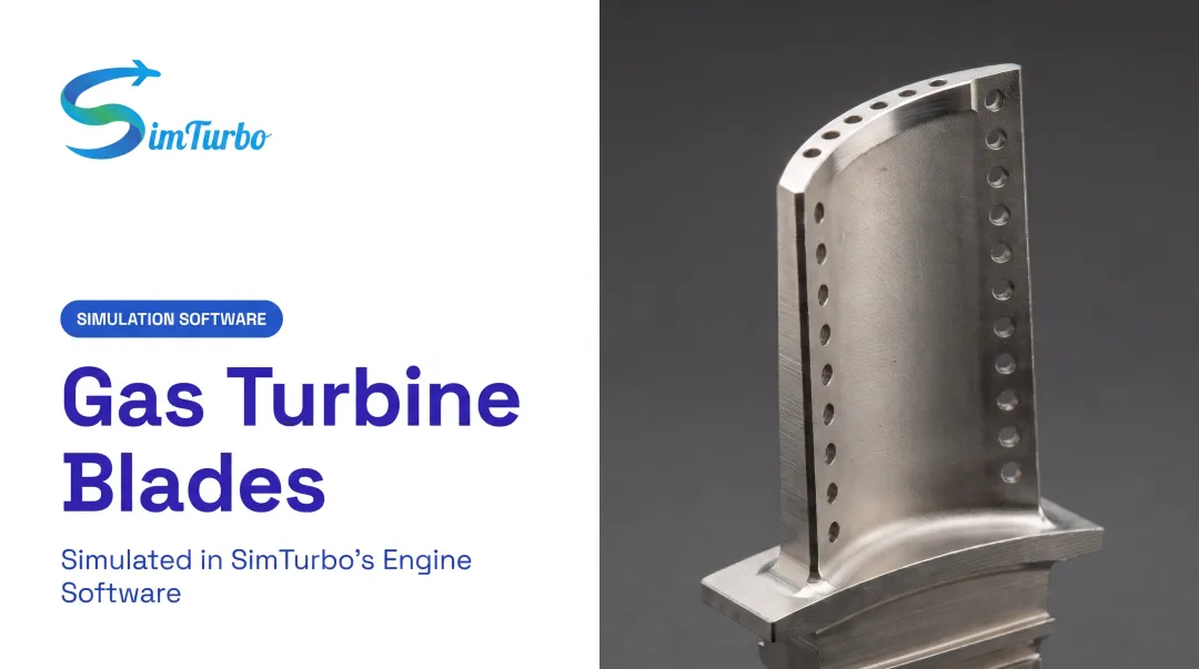
- Requires sophisticated internal cooling passages, film-cooling holes, and thermal barrier coatings
- Nickel-base superalloys (containing >50% Ni) are cast as directionally solidified or single-crystal structures to resist creep
Low-pressure turbine (LPT):
- Operates at lower gas temperatures (900–1,200°C) but larger span and higher mass flow
- Weight and centrifugal load are critical; lighter materials reduce disk stress
- GE's second-stage CMC LPT blade weighed one-third its metal predecessor and required no air cooling, raising aerodynamic efficiency
- Typically 4–7 stages in modern turbofans to maximize expansion work
- Tip clearance and flutter remain key design constraints
Specialized Blade Configurations
Variable geometry blades:
Variable inlet guide vanes (VIGV) and variable stator vanes adjust metal angle during part-load or transient operation. That keeps incidence near optimal and protects stall margin.
On GE's LM6000, the VIGV system closes vanes during major power reductions. The integrated VIGV/EFS package delivered more than 2% fuel-efficiency improvement at 70% power plus 2 MW average power increase. That gain reflects the combined upgrade, not vane adjustment alone.
Critical Design Parameters
Blade efficiency, durability, and operability rest on a tight set of geometry, material, cooling, and clearance choices. The parameters below drive aerodynamic loss, structural life, and how much turbine inlet temperature the engine can actually use.
Blade Geometry and Aerodynamic Profile
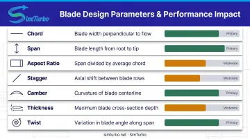
| Parameter | Definition | Impact on Performance |
|---|---|---|
| Chord | Leading-to-trailing edge reference length | Sets Reynolds number, diffusion length, structural depth |
| Span (blade height) | Hub-to-tip radial extent | Defines annulus area, aspect ratio, endwall-loss fraction |
| Aspect ratio | Span ÷ chord | Higher values reduce endwall area but increase slenderness/vibration risk |
| Stagger | Chord orientation to axial direction | Controls incidence, throat area, flow capacity, turning |
| Camber | Mean-line curvature | Higher camber increases turning but raises separation risk |
| Thickness distribution | Pressure-to-suction surface spacing | Affects leading-edge tolerance, peak Mach number, stress, cooling-passage space |
| Twist | Radial change in metal angle | Matches changing blade speed and velocity triangles from hub to tip |
Airfoil profiles divide into subsonic diffusion types and transonic profiles with passage shocks. A 2021 ASME study identifies shock/suction-side boundary-layer interaction as the source of high unsteadiness and loss in transonic compressors. Designers must control shock position and boundary-layer state to limit those penalties.
Material Selection and Structural Integrity
Material families and applications:
- Nickel-base superalloys (HPT): Single-crystal or directionally solidified castings resist creep, oxidation, and thermal fatigue; must meet FAA-approved design properties
- Titanium alloys (cooler compressor sections): Ti-6Al-4V offers comparable strength at 60% of steel's density, but oxidation above 600°C limits use to front/mid compressor stages
- SiC/SiC ceramic matrix composites (emerging LPT): Up to about 280°C (500°F) more heat capability and one-third the weight of metal; cuts centrifugal load and can remove cooling demand in some stages
FAA 14 CFR 33.15 mandates that materials demonstrate suitability through experience or test and conform to approved specifications. Generic temperature limits do not replace alloy-specific, mission-validated allowables.
Cooling and Thermal Management
Turbine blade cooling techniques:
- Internal passages: Serpentine channels with turbulators, jet impingement on leading/trailing edges
- Film cooling: Shaped diffusion holes at midchord; coolant exits to form protective surface layer; poor momentum ratio causes lift-off and mixing loss
- Thermal barrier coatings (TBC): Ceramic topcoat plus metallic bond coat reduce substrate heat flux; NASA's 10 mol% YbGd-YSZ coating demonstrated thermal stability to 1,650°C in test
Effective cooling raises turbine-inlet temperature and cycle efficiency. Every cooling feature still costs performance: compressor bleed for coolant cuts net thrust and raises fuel burn. Designers balance coolant flow, hole geometry, and passage layout so metal temperature drops without excess aerodynamic loss.

Tip Clearance and Secondary Flow Effects
Radial blade-tip-to-case gap must remain tight to limit pressure leakage while preventing mechanical rub. Excessive clearance allows high-pressure gas to bypass the blade tip, rolling into a leakage vortex that unloads the tip, mixes out downstream, and can interact with passage shocks.
NASA's 2016 integrated model cites legacy experiments showing a 6.8% clearance-to-passage-height increase correlating with 20% turbine-efficiency loss. The same model projects up to 1% mission-efficiency improvement for a 10 mil (0.25 mm) reduction. Both figures are experiment-specific sensitivities, not universal penalties.
Secondary flow phenomena:
- Tip leakage vortices: Pressure-side-to-suction-side flow at blade tip
- Endwall flows: Boundary layers plus cross-passage pressure gradients generate passage vortices and corner separation
- Mitigation strategies: 3D lean/sweep, endwall contouring, controlled loading distribution, active clearance control
Blade Design Optimization Techniques
Computational Fluid Dynamics (CFD) Approaches
CFD hierarchy for blade analysis:
- Throughflow/mean-line: Architecture and stage count
- Steady RANS: Routine blade-to-blade design, pressure distributions, loss
- Mixing-plane or harmonic: Multistage interaction
- URANS: Wakes, shocks, forced response
- LES/hybrid RANS-LES: Detailed unsteady-loss questions
Higher-fidelity steps only pay off when the setup is validated. A NASA Glenn-HT study solved finite-volume compressible RANS with second-order upwind convection, explicit Runge-Kutta, and multigrid on 2M/7M-node grids (near-wall y⁺ ≈ 1).
Exit-angle agreement was mostly ±1° at cruise and under 2° at takeoff. A missed suction-side separation drove pressure and loss error, so turbulence-model choice and grid resolution still decide whether the prediction is usable.
Simulation-Based Design Validation
Blade-level CFD still has to connect to engine-level behavior. Engineers use simulation to check aerodynamics, structural loads, and thermal response before committing to hardware.
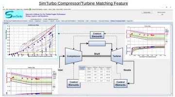
With SimTurbo, gas-turbine systems are built as interconnected components you can re-parameterize. Compressors, turbines, shafts, and controls sit on a graphical palette, and corrected mass flow, pressure ratio, operating points, and efficiency show up on interactive maps and tables in real time.
Validation observables:
- Blade static-pressure distribution
- Isentropic surface Mach number
- Exit total-pressure/loss survey
- Exit flow angle
- Performance map (pressure ratio, efficiency, flow vs. speed)
SimTurbo's J85-GE-21 validation matched NASA Lewis Research Center test data within ±2% for thrust, flow rate, temperature, and thrust-specific fuel consumption. Component-map system models can predict engine-level performance when the underlying aero and thermo relations are validated.
Multi-Objective Optimization Strategies
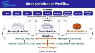
Once aero predictions are trusted, optimization has to trade more than peak efficiency. Modern blade work balances aerodynamic performance, structural integrity, manufacturability, and cost.
An ASME compressor study posted a nominal 1.65% isentropic-efficiency gain, then found higher stress and a failed vibration-frequency constraint. Aero-only maxima are not enough. Coupled structural and modal limits, and Pareto-feasible designs, deliver more usable value than a single-objective peak.
Typical optimization variables:
- Chord, sweep, lean, stagger, camber, thickness
- Endwall contouring, tip gap, cooling-hole layout
Objectives and constraints:
- Maximize efficiency, pressure ratio, flow range
- Minimize mass, stress, temperature
- Maintain frequency separation from excitation orders
- Ensure casting/machining access and cost targets
Common Blade Design Challenges
Blade design trades aerodynamic efficiency against structural life and what can be built, inspected, and certified. The issues below show up repeatedly on compressor and turbine stages.
Aerodynamic Challenges
Flow separation
- Driven by adverse pressure gradients, off-design incidence, tip leakage, or corner flow
- Mitigate by redistributing loading, raising leading-edge tolerance, optimizing solidity and camber, contouring endwalls, and scheduling variable stators
Transonic shocks
- Shock and suction-side boundary-layer interaction raises loss and unsteadiness
- Laminar interaction can form a separation bubble; shock motion drives buffeting and shifts stall onset
- Control shock position with passage geometry and boundary-layer state (transition location, turbulence intensity)
Structural Challenges
Once the aero shape is close, life and dynamics usually set the real envelope.
High-cycle fatigue (HCF) and resonance
- Map natural modes against shaft-order and blade-passing excitation on Campbell diagrams
- Evaluate mistuning and aerodynamic damping
- Run FAA vibration surveys across permitted thrust/power and rotor-speed ranges so combined steady and vibratory stress stays below endurance limits
Creep and thermomechanical fatigue
- HPT centrifugal load stacks with metal-temperature gradients and cyclic start-stop strain
- Use alloy-, coating-, environment-, and mission-specific allowables; no universal MPa or temperature cutoff applies
- Orient single-crystal grain boundaries to maximize creep resistance along principal stress directions
Flutter
- Aeroelastic instability when aerodynamic work per cycle exceeds structural damping
- Most critical in high-aspect-ratio LPT stages with low material damping
- Maintain frequency separation and positive aerodynamic damping margins
Manufacturing Constraints
Hardware reality and airworthiness rules close the loop on every blade design choice.
Casting and machining
- Control crystal orientation, wall thickness, core shift, and porosity in hollow single-crystal castings
- Preserve hole shape and limit recast-layer thickness when EDM or laser-drilling cooling holes
- Follow OEM drawing and process specs; no universal blade-casting tolerance applies
Quality control
- Dimensional metrology and airflow testing for cooling circuits
- Fluorescent penetrant inspection for surface-breaking defects
- Radiography or CT for internal structure; ultrasonic or eddy-current where qualified
- ASTM method standards apply; acceptance limits stay part-, material-, and process-specific
Certification requirements
- 14 CFR 33.19: compressor/turbine cases must contain rotor-blade damage
- 14 CFR 33.27: rotor overspeed protection
- 14 CFR 33.87: at least 150 hours of endurance testing
- 14 CFR 33.94: blade-containment demonstration tests
Frequently Asked Questions
What is the best blade design?
No single "best" design exists. Geometry depends on the application: an industrial turbine prioritizes fuel efficiency and long service life, while a fighter-engine HPT blade favors power density and transient response. Material, cooling, manufacturing limits, and cost finish the trade.
What are different types of blades?
Common types include axial compressor blades, centrifugal impellers, high-pressure and low-pressure turbine blades, and variable-geometry vanes. Each serves a different role—multi-stage diffusion, high pressure ratio per stage, hot-section work extraction, weight-sensitive LPT work, or part-load stall-margin control.
How does blade twist affect performance?
Twist varies metal angle from hub to tip so local velocity triangles stay on design incidence and loading. Done well, it cuts separation risk, raises efficiency, and balances radial pressure. Gains depend on stage, speed, and inlet conditions—not a fixed percentage.
What role does blade cooling play in turbine design?
Cooling lets turbines run at higher inlet temperatures for better cycle efficiency while limiting creep and oxidation. Passages, film holes, and TBCs drop metal temperature, but each feature bleeds compressor air and adds aero loss. GE's CMC LPT blade removed second-stage air cooling and improved efficiency.
Why is blade tip clearance critical?
Too much tip clearance leaks pressure and cuts stage efficiency and thrust; too little risks rubs during thermal growth or transients. In one NASA case, a 6.8% clearance increase cut turbine efficiency by 20%. Active clearance control trims case diameter to hold the gap across the envelope.
How do engineers validate blade designs before manufacturing?
Teams use CFD for flow and shocks, FEA for thermal/stress/modal behavior, and system simulation for matching and cycle performance. Tools like SimTurbo support real-time map checks and transient analysis before hardware spend. Final proof comes from cascade or rotating-rig tests, then full-engine endurance and FAA certification testing.
Blade design succeeds when aero, thermal, structural, and manufacturing choices line up. Teams that connect geometry to performance, pick materials and cooling with care, and validate early with simulation and rig tests ship engines that hit efficiency, power, and reliability targets in aerospace, marine, and power generation.