Engineers designing these components face a tough balancing act. Blades must survive extreme heat and centrifugal force, stay aerodynamically efficient across a range of operating conditions, and remain manufacturable within realistic budgets and timelines.
This guide breaks down blade anatomy, the aerodynamics behind airfoil shapes, the major airfoil categories, common design challenges, and how simulation platforms are changing the way engineers validate turbine performance before cutting metal.
Key Takeaways
- Turbine blades transmit centrifugal, thermal, and aerodynamic loads through three main structural zones: root, platform/shroud, and airfoil
- Airfoil shape drives lift and work extraction through pressure differences across the suction and pressure sides
- Design thickness shifts by region and stage: thicker roots for strength, thinner tips for aerodynamics
- Nickel-based superalloys, erosion, and manufacturing precision remain persistent engineering hurdles
- Simulation platforms like SimTurbo let engineers test engine and component behavior digitally before committing to hardware
What Are Turbine Airfoils and Blades
What Are Turbine Airfoils and Blades?
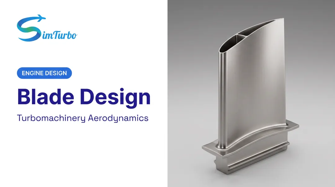
A turbine blade is the rotating component that pulls energy out of a moving fluid, whether that's combustion gas in a jet engine, steam in a power plant, or air in an industrial gas turbine. The airfoil is simply the blade's cross-sectional profile: the curved shape that actually interacts with the flow.
Anatomy: Root, Shroud, and Airfoil
Every blade has three functional zones, each engineered for a distinct job:
- Root (attachment): Anchors the blade to the rotor disk and transfers centrifugal, thermal, and bending loads into the disk.
- Platform/shroud: Sits between the root and airfoil, helping define the gas-path boundary. Some designs add an integral tip shroud or use labyrinth-style seals against the stationary casing to limit gas leakage around the blade tip.
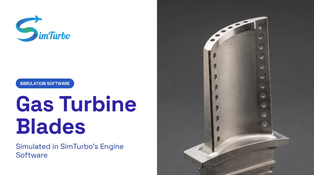
- Airfoil: The gas-facing surface with a leading edge (where flow first contacts the blade), trailing edge, suction side (low pressure), and pressure side (high pressure). Profile thickness and camber change from root to tip to balance strength against aerodynamic efficiency.
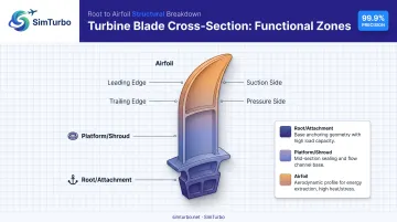
In NASA's Energy Efficient Engine high-pressure turbine, a five-tooth root attachment carried those loads without exceeding stress limits at nearly 1,093°C local metal temperature, per the NASA E3 turbine design report.
Turbine Blades vs. Compressor Blades vs. Vanes
These three components look similar but do opposite jobs:
| Component | Function | Motion |
|---|---|---|
| Turbine blade | Extracts energy from expanding hot gas | Rotates |
| Compressor blade | Adds energy to compress incoming air | Rotates |
| Vane/nozzle | Redirects flow angle, sets stage inlet conditions | Stationary |
Blade size varies enormously by application. NASA's E3 high-pressure turbine blade had an axial chord of just 2.545 cm, while a separate NASA first-stage rotor-blade model measured an 8.61 cm axial chord with a 9.15 cm pitch. That range spans small turbopump hardware through large aeroderivative rotor stages, depending on thrust class and mission (NASA E3 report).
How Airfoils Work: The Aerodynamics Behind the Shape
Lift comes from a pressure difference. Gas moving faster over the curved suction side creates lower static pressure than the slower-moving flow along the pressure side. That imbalance generates a net force NASA describes as the fundamental mechanism behind airfoil performance.
Drag works against this. It comes from surface friction and turbulence shedding off the trailing edge. In a turbine cascade, viscous boundary layers, wake mixing, and tip leakage all show up as total-pressure loss, directly cutting into stage efficiency.
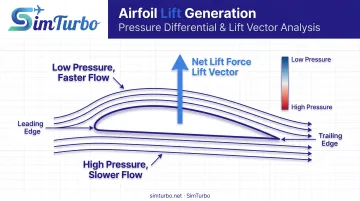
Lift-to-drag ratio is the classic aircraft efficiency metric, but turbine engineers usually judge performance differently. Rather than optimizing a single sectional L/D, they track how surface pressure and cascade flow translate into:
- Tangential force (does the actual work of spinning the rotor)
- Axial force (thrust or flow-through component)
- Stage efficiency and cascade loss coefficient
Entrance and exit angles matter just as much as shape. If a blade's inlet angle doesn't match the incoming flow from the upstream vane, energy transfer between stages suffers.
Pitch and flow-angle adjustments let some turbines adapt across varying loads, similar in principle to wind-turbine pitch control, though the mechanisms differ.
Types of Airfoils Used in Turbine Applications
Airfoils fall into three broad categories:
- Symmetric: Identical curvature on both surfaces. Generates no lift at zero angle of attack; used where flow direction reverses or stays neutral.
- Non-symmetric (cambered): Curved more on one side. Generates lift even at zero angle of attack, common in most turbine and compressor stages.
- Reflex: Curves back near the trailing edge, often used to manage pitching moment in specific configurations.
Airfoil Families by Blade Region
Thickness requirements shift dramatically along a blade's span. Root sections need extra material to handle centrifugal stress, while tip sections stay thin to minimize aerodynamic loss at higher radius.
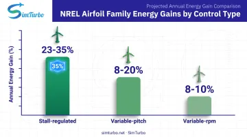
This region-specific thinking isn't new. NREL's 1995 research (NREL/TP-442-7109) developed seven purpose-built airfoil families for wind turbines, each assigning distinct root, primary, and tip sections.
Projected annual energy gains from these families ranged from 23% to 35% for stall-regulated designs, 8% to 20% for variable-pitch, and 8% to 10% for variable-rpm turbines, compared to older aircraft-derived airfoils (1995 design-study projections, not guaranteed field results).
Application-Specific Airfoil Selection
The same spanwise logic shows up in gas turbines. High-pressure and low-pressure stages demand different trade-offs:
- High-pressure stages: Face extreme heat. NASA's E3 high-pressure turbine ran at an average blade metal temperature of 954°C (1,749°F), using coated single-crystal nickel-base alloys and internal film cooling.
- Low-pressure stages: Run cooler but often prioritize weight. Titanium-aluminide blades used in some low-pressure turbine designs weigh roughly half as much as comparable nickel-alloy parts, cutting rotating mass and improving fuel efficiency.
Engineering Challenges in Blade and Airfoil Design
Thermal, mechanical, and centrifugal loads dictate both blade geometry and alloy choice at every stage. Hot-section blades need superalloys that survive near-melting temperatures; downstream stages can prioritize lighter materials since heat loads drop off.
Degradation factors compound over service life:
- Sand and particulate erosion attack trailing edges; NASA tests showed severe wear on nickel-base superalloy vanes versus negligible damage on silicon-nitride alternatives.
- Salt exposure can cut ceramic surface strength by 30–40% within a few hours at high temperature.
- Surface roughness and fouling shift downstream aerodynamic loss patterns, eroding efficiency even without visible damage.
Manufacturability is just as constraining as the thermal environment. Nickel-based superalloys keep their strength at high temperature, which is why designers specify them. That same strength makes them hard to machine. Low thermal conductivity, hard intermetallic phases, and work hardening accelerate cutting-tool wear. Hitting aerospace and power-generation tolerances still requires tight process control and inspection.
How Simulation Software Accelerates Turbine Airfoil Design
Traditional blade validation relied heavily on prototype-and-test cycles: build hardware, run it, measure results, iterate. That approach is accurate but slow and expensive, especially early in design when engineers are still exploring geometry and operating envelopes.
Component-based simulation platforms shorten that loop. Instead of treating the engine as a sealed black box, engineers model inlets, compressors, combustors, turbines, nozzles, and shafts individually, then connect them on a design palette. Blade and stage assumptions—efficiency, matching, temperature limits—show up immediately in system thrust, EGT, and fuel burn, so weak airfoil directions get dropped before metal is cut.
SimTurbo, a Windows-based gas turbine simulation platform from Controls Research LLC, is built for that workflow. Engineers and students can:
- Build single-spool or dual-spool turbojet models component by component
- Watch transient and steady-state performance in real time (RPM, EGT, thrust, SFC)
- Validate control laws using built-in PID controllers, limiters, actuators, and sensors
- Export time-series results to CSV and Excel for further post-processing
SimTurbo's steady-state results were benchmarked against NASA Lewis Research Center's J85-GE-21 test data, landing within ±2% accuracy for thrust, flow rate, temperature, and thrust-specific fuel consumption.
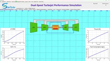
Physical testing still matters. The gain is earlier: engineers can screen blade concepts, refine the promising ones, and spend rig time on designs that already clear system-level checks.
Frequently Asked Questions
What airfoil do wind turbines use?
Modern wind turbines typically use NREL-developed airfoil families, with separate root, primary, and tip sections designed together for the rotor's size and control strategy. These differ from the aircraft-derived NACA sections used in earlier wind turbine designs.
What is the purpose of a turbine blade?
A turbine blade converts the kinetic and thermal energy of a moving fluid, such as combustion gas or steam, into rotational torque. That torque drives a shaft connected to a compressor, fan, or generator.
How do airfoils actually work?
Airfoils generate lift through a pressure difference: faster flow over the curved surface creates lower pressure than the slower flow on the opposite side. Angle of attack and profile shape both control how much lift and drag result.
What are the three main types of airfoils?
- Symmetric: Matching curvature on both sides; no lift at zero angle of attack
- Cambered: More curve on one side; lifts even at neutral angle
- Reflex: Curves back near the trailing edge to manage pitching moment
How do engineers validate turbine blade designs before manufacturing?
Engineers combine computational simulation with physical wind tunnel or rig testing. Platforms checked against known engine test data, such as SimTurbo's NASA J85-GE-21 validation, build confidence before hardware commitments.