Introduction
An engineer designing a new gas turbine configuration for cruise conditions needs to know whether the system will operate efficiently before committing resources to physical prototyping. The first question isn't how the engine responds during acceleration—it's what happens when everything stabilizes. That is where steady-state analysis becomes indispensable.
Steady-state analysis evaluates system behavior under constant operating conditions: all variables have settled, and time-dependent changes have dissipated. It gives engineers a baseline for how a gas turbine performs at cruise power, how a compressor matches its turbine, and whether design choices will hit performance targets.
This article covers:
- Definition and mathematical basis of steady-state analysis
- Applications across engineering, with emphasis on gas turbine systems
- How steady-state analysis differs from transient analysis
- Practical workflow steps for faster, clearer design decisions
Key Takeaways
- Captures equilibrium conditions when all system variables stay constant over time
- Validates design choices, component sizing, and performance baselines before transient work
- Quantifies pressure ratios, temperatures, fuel consumption, and efficiency at key operating points
- Anchors transient analysis, control system design, and dynamic stability studies
What Is Steady-State Analysis?
Fundamental Definition and Mathematical Representation
Steady-state analysis examines a system when its variables—temperature, pressure, flow rate, shaft speed—no longer change with time. Mathematically, this means the partial derivative of any property with respect to time equals zero: ∂p/∂t = 0, ∂T/∂t = 0, and so on.
In practical engineering terms, steady state is the settled condition after startup effects have dissipated. A gas turbine at cruise power, for example, holds constant thrust, fuel flow, and turbine temperatures once transients fade.
Contrast this with transient operation, where variables change continuously—engine acceleration, throttle changes, or startup sequences all involve time-dependent behavior that steady-state analysis cannot capture.
Core Characteristics of Steady-State Systems
Three traits define steady-state behavior in open turbomachinery systems:
- Continuous flow at balance: A compressor at fixed speed with steady inlet and outlet flow keeps mass in and mass out equal, so internal properties stay constant.
- Constant at stations, not particles: Fluid particles still accelerate and change properties as they move. What stays fixed are properties at fixed locations—station 3 (compressor exit) holds the same pressure and temperature over time.
- Steady state ≠ equilibrium: Steady state can exist in open systems with continuous flow. Thermodynamic equilibrium usually means a closed system with uniform properties and no driving forces. A flowing gas turbine can be steady without being in equilibrium.
Linear vs. Non-Linear Steady-State Analysis
Linear steady-state analysis treats material properties and system parameters as independent of the solution, which yields simplified models for early design. You solve the equations once and get the answer.
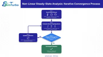
Real gas turbines are non-linear. Thermal conductivity varies with temperature, compressor performance depends on pressure ratio and corrected speed, and turbine efficiency shifts with operating point. Those couplings need iteration: seed initial values, evaluate the governing equations, update the estimates, and repeat until the solution converges.
NASA gas turbine models often use Newton-Raphson or secant methods to find steady-state points that satisfy mass, energy, and momentum conservation while matching non-linear component performance maps.
Applications Across Engineering Disciplines
Steady-state analysis appears throughout engineering:
- Electrical engineering: AC circuit analysis at constant frequency
- Mechanical engineering: Vibration systems at steady amplitude
- Thermal engineering: Heat transfer with constant boundary conditions
- Fluid dynamics: Pipe flow with time-invariant pressures and velocities
Gas turbine work pulls these domains together—thermodynamics, fluid mechanics, and heat transfer—so steady-state matching has to satisfy all of them at once. The same rules (time derivatives at zero, conservation laws, and component matching) underpin cycle decks, control setpoints, and performance maps used in aero and power-generation engines.
Why Steady-State Analysis Matters in Engineering
Design Decision Foundation
Steady-state analysis provides the baseline understanding of how a system performs under normal, sustained operating conditions. Engineers use these results to:
- Size components (compressor diameter, turbine blade count)
- Select materials that withstand predicted temperatures and stresses
- Make architecture decisions early in the design process
Steady-state analysis also runs much faster than transient simulation because it skips time-stepping through dynamic behavior. That speed supports rapid iteration in conceptual and preliminary design, when teams need to compare many configurations quickly.
Determining compressor pressure ratio requirements for a turboshaft engine at rated power (a steady-state question) takes minutes. Simulating the full startup sequence to that same power level needs a transient model and far more compute time. Because each run finishes quickly, teams can evaluate more design alternatives and push optimization further inside the same schedule and budget.
Performance Prediction and Validation
Steady-state analysis predicts key metrics at specified operating points:
- Efficiency (thermal, component-level)
- Power output or thrust
- Fuel consumption and specific fuel consumption
- Thermal loads and component temperatures
Manufacturers use steady-state analysis to create performance maps that show engine behavior across the operating envelope: thrust versus altitude and Mach number, fuel consumption versus shaft speed, and temperature limits across ambient conditions.
Steady-state predictions also compare directly against test data from engine runs at stabilized conditions. NASA's J85-based model, for instance, matched design criteria to better than 1% on key parameters, including thrust (0.3%), SFC (0.01%), and turbine-inlet temperature (0.14%).
Baseline for Advanced Analysis
Transient analysis typically begins from a steady-state initial condition. Startup sequences, throttle transients, and failure scenarios all start from a known, converged operating point, and the steady-state solution supplies that starting point.
Control system design depends on the same operating points. Engineers design controllers to hold or move between these states, and dynamic stability work studies how the system responds to small perturbations around steady-state equilibrium.
For engines that spend most of their life at steady conditions (cruise flight, continuous power generation), these converged results are also the most operationally relevant design data you can get early.
Steady-State Analysis in Gas Turbine Systems
Gas Turbine Operating Points and Steady-State Conditions
Gas turbines operate at various steady-state points:
- Idle: Minimum stable operating speed
- Cruise: Primary mission condition for aircraft engines
- Maximum continuous power: Highest sustainable output
- Design point: The specific condition (altitude, Mach number, ambient temperature) for which the engine is optimized
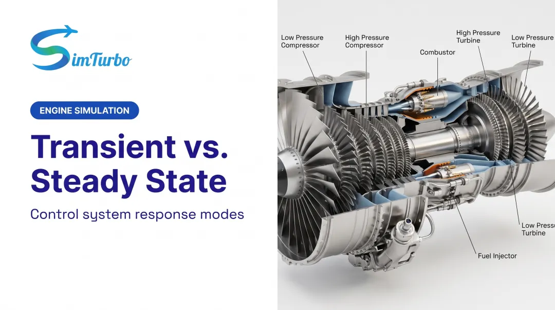
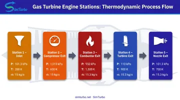
Steady-state analysis determines the thermodynamic state at each station through the engine: inlet, compressor exit, combustor exit, turbine exit, and nozzle. For a design-point analysis, engineers select cycle parameters and size components at the primary mission condition (e.g., Mach 0.8 and 35,000 ft for a jet engine).
Component-Level Steady-State Behavior
Compressor analysis covers:
- Pressure ratio and temperature rise
- Efficiency and corrected mass flow
- Operating point on the compressor map
- Surge margin (distance from the stall line)
In the combustor, steady-state work centers on:
- Fuel flow required to hit target turbine inlet temperature
- Combustion efficiency and pressure loss
- Stability margins at the operating condition
Turbine analysis then checks:
- Power extraction and expansion ratio
- Efficiency and corrected flow
- Matching with compressor power requirements
Shaft dynamics close the loop: steady-state analysis enforces power balance so turbine power equals compressor power plus accessory loads plus net output (thrust or shaft power).
Performance Parameters from Steady-State Analysis
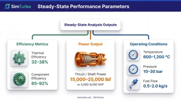
Key outputs include:
- Thrust or shaft power at specified conditions
- Specific fuel consumption (fuel flow per unit thrust or power)
- Thermal efficiency and component efficiencies
- Operating temperatures and pressures throughout the engine
- Airflow and corrected parameters
Teams use these outputs to set design targets, write customer performance specs, and support certification evidence.
Off-Design Steady-State Analysis
Design point versus off-design: Design-point analysis optimizes the engine for one specific condition. Off-design analysis predicts performance at any other operating condition, including different altitudes, speeds, ambient temperatures, or power settings.
Component matching determines how the compressor, turbine, and other components work together at off-design conditions. Because component efficiencies and flow capacities vary with operating point, off-design analysis requires performance maps and iterative matching to find the converged solution.
Performance maps show thrust, fuel consumption, and temperatures across the operating envelope, which feed control system development and operability assessment.
Validation and Accuracy Considerations
Well-calibrated steady-state models can achieve high accuracy when validated against engine test data. Published examples report:
- NASA J85-based model: Below 1% for all design parameters; thrust 0.3%, SFC 0.01%
- NASA T-MATS versus NPSS comparison: Below 0.5% for all parameters; thrust 0.15%
These figures reflect code-to-code verification or design-point matching cases. Accuracy depends on:
- Quality of component performance maps
- Precision of thermodynamic property calculations
- Proper accounting for losses and installation effects
Educational Applications in Gas Turbine Analysis
Universities use steady-state gas turbine analysis to teach:
- Thermodynamic cycles (Brayton cycle, component processes)
- Component matching and system integration
- Design trade-offs and cause-effect relationships
Students can quickly explore parametric studies by varying pressure ratio, turbine inlet temperature, or component efficiencies, then immediately see the impact on thrust, efficiency, and fuel consumption. Visualization tools that display state changes through the engine and performance maps make abstract thermodynamics concepts concrete.
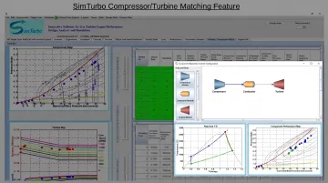
SimTurbo provides a Windows-based environment for that exploration, with real-time thermodynamic cycle diagrams (Temperature-Entropy and Pressure-Volume plots), component maps, and performance graphs. Students assemble engine configurations from modular components, run steady-state cases across corrected speeds, and watch thermal efficiency and thrust-specific fuel consumption respond directly.
When to Use Steady-State vs. Transient Analysis
Use steady-state analysis when:
- Evaluating sustained operating conditions (cruise, maximum continuous power, idle)
- Confirming the system has reached equilibrium after transients dissipate
- Asking what happens once the system stabilizes at a given condition
- Basing design decisions on performance at specific operating points
- Establishing initial conditions for later transient studies
Use transient analysis when:
- Modeling startup sequences, throttle changes, or acceleration/deceleration
- Assessing emergency shutdown or failure response
- Evaluating control system dynamic response
- Letting time-dependent behavior drive the engineering decision
- Asking how the system moves from condition A to condition B
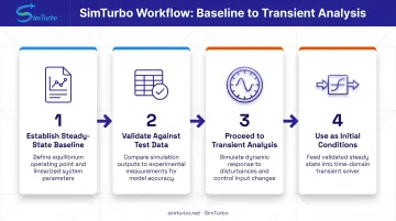
Typical workflow strategy:
- Start with steady-state analysis to establish baseline performance
- Validate the steady-state model against test data or published specifications
- Proceed to transient analysis when time-dependent phenomena become important
- Use converged steady-state solutions as initial conditions for transient runs
NASA's T-MATS workflow follows the same path: engineers first built and matched a turbojet in steady state, then added shaft-speed integration and a controller to create the dynamic model.
Tools and Software for Steady-State Analysis
Categories of Steady-State Analysis Tools
Engineers choose from several tool types depending on fidelity requirements and analysis scope:
- Specialized gas turbine performance software: Purpose-built for cycle analysis and component matching
- General thermodynamic cycle tools: Flexible platforms for various heat engine cycles
- Computational fluid dynamics (CFD): High-fidelity component analysis (single blade row, combustor flow field)
- Integrated simulation environments: Combined steady-state and transient capability
Tool selection depends on the level of component detail needed, whether coupled analysis (thermal-structural, aero-mechanical) is required, and how results will be used downstream.
Software Capabilities for Gas Turbine Steady-State Analysis
Essential features engineers need:
- Component performance modeling (compressors, turbines, combustors, heat exchangers)
- Thermodynamic property libraries for air and combustion products
- Solver algorithms for component matching and power balance
- Visualization of results (cycle diagrams, performance maps, station data)
SimTurbo is one Windows-based environment built for those needs. Its component-based architecture lets engineers configure turbojet, turboshaft, and recuperated cycles, then evaluate steady-state performance across the operating envelope.
The same platform also supports transient simulation, so design-point work and dynamic studies stay in one model.
Key capabilities include:
- Drag-and-drop component assembly (inlets, compressors, combustors, turbines, nozzles, recuperators, afterburners)
- Real-time thermodynamic visualization (T-S and P-V diagrams)
- Component performance maps with operating-point tracking
- Off-design analysis across altitude, Mach number, and ambient conditions
- Validation against NASA test data (J85-GE-21 within ±2% for thrust, flow rate, temperature, and TSFC)
Integration with Engineering Workflow
Steady-state analysis results feed into multiple downstream activities:
- Design reviews and performance specifications
- Control system development (operating points, power balance, temperature limits)
- Test planning (expected performance, instrumentation requirements)
- Certification and customer documentation
SimTurbo exports performance data for post-processing in MATLAB, Excel, or Python, so engineers can build custom plots, run extra calculations, and fold results into broader system studies.
Frequently Asked Questions
What is steady-state analysis?
Steady-state analysis evaluates system behavior when all variables remain constant over time. It describes equilibrium conditions where inputs balance outputs and time-dependent changes have ceased.
What is an example of a steady state?
A gas turbine engine at cruise power is a clear example: shaft speed, fuel flow, temperatures, and pressures stay constant while the engine produces steady thrust. Throttle transients have dissipated, and the system has settled into a stable operating condition.
How do you calculate steady state?
Set time derivatives to zero in the governing equations for mass, energy, and momentum. Engineers then use iterative methods such as Newton-Raphson to satisfy component maps, physical constraints, and boundary conditions until residuals converge.
When should I use steady-state analysis instead of transient analysis?
Use steady-state analysis for sustained operating conditions, equilibrium-based design decisions, or as initial conditions for transient studies. Choose transient analysis for startup, shutdown, acceleration, control response, or other time-critical scenarios.
What are the limitations of steady-state analysis?
Steady-state analysis cannot predict time-dependent behavior such as startup sequences, throttle transients, or failure response times. It also misses dynamic stability and how quickly a system reaches equilibrium, so rapid-change or control-dynamics questions need transient analysis.
How accurate is steady-state analysis for gas turbine systems?
Accuracy depends on component model fidelity, property data, and loss accounting. Well-calibrated models validated against test data can match design parameters within ±2%, though results still vary by operating point and calibration quality.