Regeneration solves this problem by capturing waste heat from turbine exhaust and using it to preheat compressed air before combustion, reducing fuel consumption significantly. By recovering thermal energy that would otherwise be lost to the environment, regenerative cycles improve both economic performance and environmental sustainability across marine propulsion, distributed power generation, and industrial cogeneration applications.
Key Takeaways
- Regeneration recovers waste exhaust heat to preheat compressed air, improving thermal efficiency by 7-10 percentage points
- Counterflow regenerators must approach 85-90% effectiveness for microturbines to reach 40% efficiency
- Delivers peak gains when turbine exhaust temperature exceeds compressor discharge temperature at moderate pressure ratios
- Pairs with intercooling and reheat to approach ideal thermodynamic cycle limits
- Applications include naval vessels, recuperated microturbines, and industrial CHP systems
What Is a Regenerative Gas Turbine Cycle?
Definition and Fundamental Concept
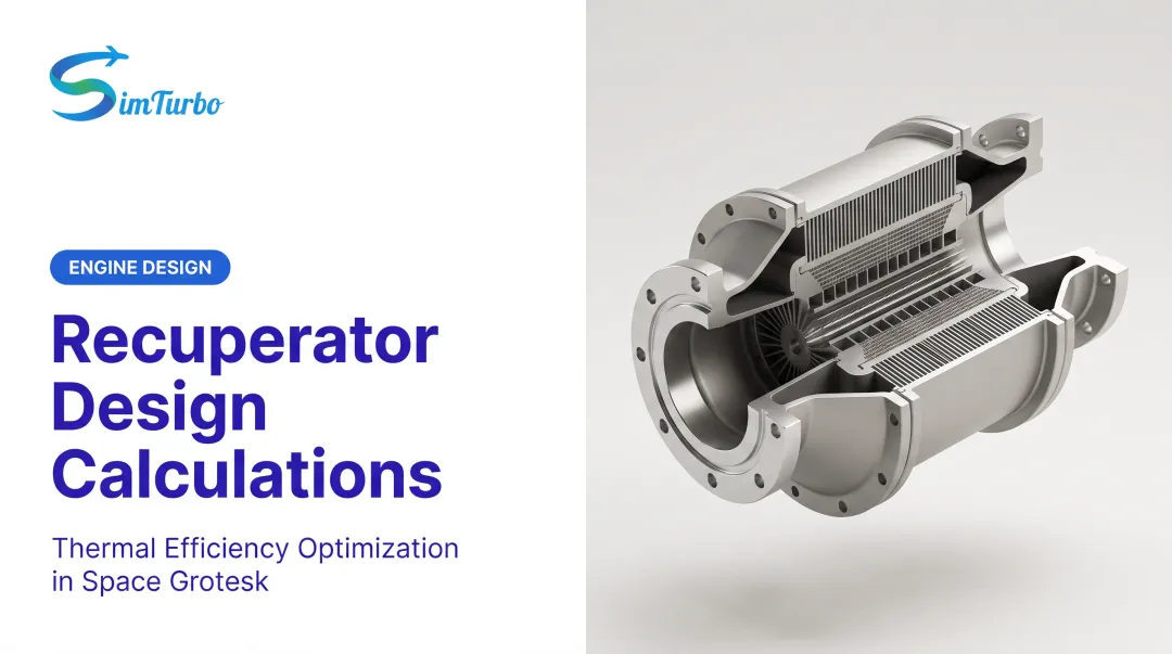
A regenerative cycle is a modified Brayton cycle incorporating a heat exchanger—called a regenerator or recuperator—that transfers thermal energy from turbine exhaust to compressor discharge air. This reduces the amount of fuel needed to reach the selected turbine-inlet temperature, directly improving fuel efficiency.
Reducing the temperature difference between heat addition and heat rejection raises cycle efficiency. Instead of adding all combustion heat to air at compressor discharge temperature, regeneration preheats that air closer to combustion temperature with otherwise-wasted exhaust energy.
Comparison with Simple Brayton Cycle
Performance: Simple vs. Regenerative Cycle
| Metric | Simple Cycle | Regenerative Cycle |
|---|---|---|
| Thermal Efficiency | 30.2% | 37.8% |
| Pressure Ratio | 10:1 | 10:1 |
| Turbine Inlet Temperature | 1478 K | 1478 K |
| Regenerator Effectiveness | N/A | 80% |
NASA analysis at pressure ratio 10:1, turbine-inlet temperature 1478 K, and 80% regenerator effectiveness calculated 30.2% simple-cycle efficiency versus 37.8% recuperated-cycle efficiency—a 7.6 percentage-point improvement.
That gain comes from heat the simple cycle throws away. In a standard Brayton cycle, exhaust leaves at 500–600°C; a regenerative cycle captures that energy and returns it to the compressor discharge stream.
Temperature-Entropy Diagram Analysis
The T-S diagram for a regenerative cycle shows how heat recovery changes the thermodynamic process:
- Process 1-2: Isentropic compression
- Process 2-x: Regenerative heating (air absorbs exhaust heat)
- Process x-3: Combustion heat addition
- Process 3-4: Isentropic expansion
- Process 4-y: Regenerative cooling (exhaust transfers heat)
- Process y-1: Heat rejection
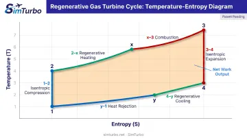
Processes 2-x and 4-y shrink the area under the heat-addition curve, so less fuel is required to reach the same turbine inlet temperature.
How Regeneration Works: The Heat Recovery Process
The Regenerator vs. Recuperator
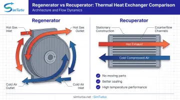
Two heat-exchanger types handle regeneration:
Regenerators use a single rotating thermal mass with alternating flow paths. Hot exhaust gases heat the matrix, which then rotates into the airstream and releases stored heat.
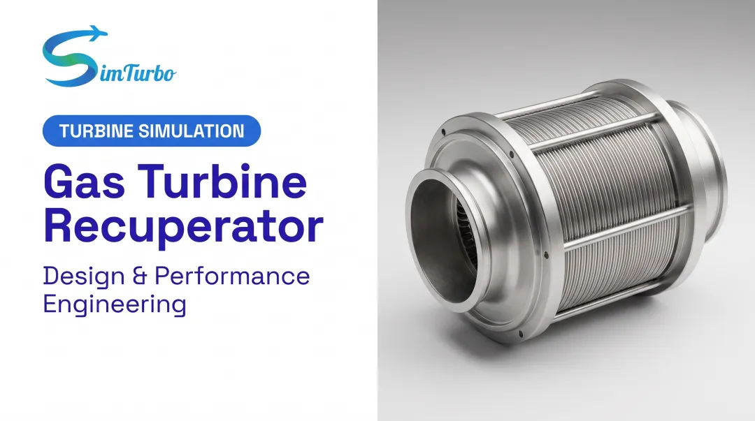
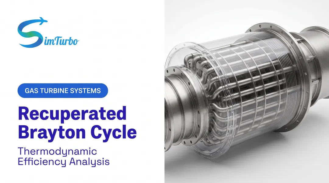
Recuperators feature stationary construction with separate continuous flow paths for hot and cold streams. Heat transfers across a fixed wall separating the two flows.
Recuperators dominate modern gas turbines. They offer:
- No moving parts
- Better sealing and reduced leakage
- Stronger performance at high temperatures
Heat Transfer Mechanism
Most recuperators use a counterflow arrangement, with shell-and-tube, plate-fin, or primary-surface designs. In counterflow, hot exhaust (typically 450–600°C) runs opposite compressed air (200–400°C). That layout keeps a strong temperature difference along the full exchanger length.
Approach temperature—the gap between cold-stream outlet and hot-stream inlet—sets how much heat the recuperator can move. Smaller approach temperatures improve recovery, but they need larger, costlier exchangers.
Regenerator Effectiveness
Effectiveness compares actual recuperator performance to the theoretical maximum:
ε = (T₅ - T₂) / (T₄ - T₂)
Where:
- T₂ = Compressor discharge temperature
- T₄ = Turbine exhaust temperature
- T₅ = Regenerator air outlet temperature
NASA analyses used effectiveness values of 70-90% in open-cycle studies and 80-95% in helium-cycle models. Higher effectiveness yields greater fuel savings but requires larger heat exchangers with increased pressure drop.
That trade-off scales fast. Per NASA mass computation models, a 95%-effective recuperator needs about twice the heat-transfer area and mass of a 90%-effective unit.
Critical Temperature Requirements
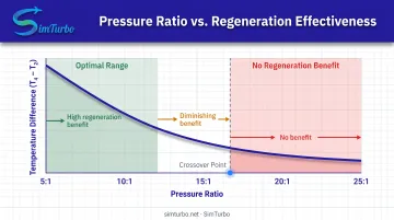
Regeneration works only when turbine exhaust temperature (T₄) exceeds compressor discharge temperature (T₂). Pressure ratio decides whether that condition holds:
- Low ratios (5:1 to 12:1): T₄ stays well above T₂, so regeneration pays off
- High ratios (above 20:1): T₂ approaches or exceeds T₄, and the benefit disappears
NASA defines crossover as the pressure ratio where turbine-exit and compressor-discharge temperatures become equal.
In helium cycles with temperature ratios of 3 and 4, crossover fell near pressure ratios of 3.7 and 5.4. The exact point still depends on turbine-inlet temperature, component efficiencies, and gas properties.
Pressure Losses and Parasitic Effects
Those heat-transfer gains come with a cost: pressure drop on both air and gas sides. NASA varied total recuperator loss from 2–4%; the 3% case split into 1.2% cold-side and 1.8% hot-side losses. Those penalties cut cycle work output.
The EPA CHP catalog reports recuperator and duct losses can cut microturbine output by 10–15% and trim a few efficiency points. Fuel savings still usually justify the hardware, especially where fuel dominates lifecycle cost.
Performance Benefits and Efficiency Gains
Thermal Efficiency Improvements
Regeneration delivers substantial efficiency gains at optimal pressure ratios. In addition to the 30.2% to 37.8% improvement shown earlier, NASA modeled efficiency at 1644 K turbine inlet temperature:
| Cycle | Thermal efficiency |
|---|---|
| Simple cycle | 33.5% |
| Recuperated cycle | 37.6% |
These gains occur because regeneration cuts the fuel energy required per unit of work output. Preheated air entering the combustor already carries heat recovered from the exhaust, so less fuel is needed to reach the same turbine inlet temperature.
Fuel Consumption Reduction
Lower heat input shows up directly as lower fuel burn. The WR-21 marine turbine design study projected 30% annual ship-profile fuel savings versus simple-cycle operation—material cost relief over multi-decade naval and commercial marine service lives.
In distributed generation and industrial CHP, the same fuel reduction improves project economics and cuts CO₂ per unit of useful energy delivered.
Exhaust Temperature Reduction
Heat recovered upstream also leaves less energy in the stack. Recuperated systems therefore exhaust much cooler than simple cycles:
| Engine | Configuration | Exhaust temperature |
|---|---|---|
| Solar Mercury 50 | Recuperated | 690°F (365°C) |
| LM2500 | Simple cycle | 1051°F (566°C) |
That 200°C+ drop lowers thermal pollution. It can also ease NOₓ formation potential, though actual emissions still depend heavily on combustor design.
Design Considerations and Regenerator Effectiveness
Pressure Ratio Optimization
Regenerative cycles exhibit an inverted-U relationship between pressure ratio and efficiency, with peak efficiency occurring near 10:1 for non-intercooled designs. This contrasts sharply with simple cycles, where efficiency generally increases with pressure ratio.
The optimum reflects competing effects:
- Lower pressure ratios create large temperature spreads (T₄ - T₂) favoring regeneration
- Higher pressure ratios increase Brayton-cycle baseline efficiency but reduce regeneration benefit
- Crossover where T₄ equals T₂ sets the upper pressure-ratio limit
Engineers selecting regenerative cycles prioritize fuel efficiency over maximum specific power output. Applications with high annual operating hours, expensive fuel, or strict emissions limits benefit most.
Material and Temperature Limits
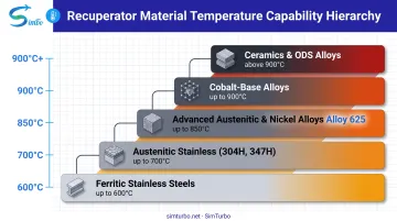
Commercial primary-surface recuperators commonly use 3-5 mil Type 347 stainless foil and operate below approximately 650°C. Material temperature ceilings include:
- 600°C: Ferritic stainless steels
- 700°C: Austenitic stainless steels (304H, 347H)
- 800-850°C: Advanced austenitic and nickel alloys
- 900°C: Cobalt-base alloys
- Above 900°C: Ceramics or oxide-dispersion-strengthened alloys
Solar's Mercury 50 uses Alloy 625 primary-surface recuperators for 600-750°C operation, with oxidation tests conducted at 704-815°C for as long as 15,000 hours.
Durability challenges include creep, thermal-cycling fatigue, oxidation, corrosion cracking, and leakage. Material selection balances temperature capability, cost, fabricability, and service life.
Integration with Control Systems
Maintaining turbine-exhaust and recuperator-inlet temperature improves part-load efficiency, so effectiveness cannot be treated as load-independent. Control systems must monitor recuperator temperatures, pressure drops, and performance degradation.
Simulation tools let engineers model regenerative cycle performance across operating conditions, optimize control strategies, and validate design effectiveness before physical prototyping.
SimTurbo, for example, supports recuperated cycle modeling with real-time thermodynamic cycle diagrams and a component-based architecture. Transient analysis helps engineering students and researchers explore effectiveness trade-offs through virtual prototyping.
Advanced Configurations: Intercooling, Reheat, and Combined Cycles
Regeneration pairs cleanly with other cycle changes. Intercooling and reheat reshape the temperatures that feed the regenerator; combined cycles put exhaust heat to work in a separate bottoming cycle instead.
Regeneration with Intercooling
Intercooling between compressor stages cuts compression work and lowers compressor discharge temperature (T₂). That widens the temperature spread (T₄ − T₂) available for regeneration.
Air is partially compressed, cooled in an intercooler toward ambient, then compressed further before it enters the regenerator.
NASA's intercooled-regenerated model reached 41.0% efficiency at a 20:1 pressure ratio, about 3.6 points above recuperation alone. The optimum pressure ratio also moved up to 20:1, widening the useful operating range.
Regeneration with Reheat
Reheating between turbine stages raises turbine exhaust temperature (T₄), so more heat remains available for the regenerator. Gas expands in a high-pressure turbine, is reheated in a secondary combustor, then expands again in a low-pressure turbine.
ASME research shows stronger part-load behavior for intercooled-reheat-regenerated layouts. Exact efficiency gains still track component design and the duty cycle you run.
Combined Cycles
In a combined cycle, gas-turbine exhaust feeds a heat-recovery steam generator and steam turbine (Brayton + Rankine). Heat that a regenerator would recover inside the gas turbine is used in the bottoming cycle instead. Modern utility plants routinely clear 60% overall efficiency with this arrangement.
Regeneration suits compact or mobile engines; combined cycles suit large stationary plants where a steam bottoming cycle is practical.
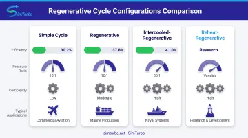
Comparison of Regenerative Cycle Variations
| Configuration | Efficiency (Modeled) | Pressure Ratio | Complexity | Applications |
|---|---|---|---|---|
| Simple Cycle | 30.2% | 10:1 | Low | Peaking power, aircraft |
| Regenerative | 37.8% | 10:1 | Moderate | Marine, distributed generation |
| Intercooled-Regenerative | 41.0% | 20:1 | High | Naval propulsion, industrial CHP |
| Reheat-Regenerative | Not validated | Variable | High | Research, specialized applications |
All efficiency figures from NASA modeling at 1478 K turbine inlet temperature with 80% regenerator effectiveness. Combined-cycle plant efficiencies are not included here; they reflect a different exhaust-heat path than on-engine regeneration.
Applications in Modern Power Systems
Marine Propulsion
The Rolls-Royce WR-21 intercooled-recuperated marine turbine, rated at 21.6 MW with greater than 88% design recuperator effectiveness, equips Type 45 destroyers. Space and weight constraints are manageable on ships, while fuel cost savings justify regenerator investment over multi-decade service life.
Naval vessels gain extended range and fewer refuelings. Commercial ships cut fuel spend and emissions under tighter marine regulations.
Distributed and Industrial Power Generation
A 2005 technical review describes recuperated microturbines at about 30% electrical efficiency versus roughly 20% without recuperation. Typical pressure ratios sit near 3–4, with recuperator effectiveness targets of at least 90%.
Solar's recuperated Mercury 50 is rated 4,600 kWe with heat rate 8,865 Btu/kWh and has documented CHP service at a Veterans Administration hospital. These medium-scale turbines (1-10 MW) serve refineries, chemical plants, and manufacturing facilities where process heat and power are both required.
Educational and Research Applications
Universities use regenerative cycle analysis in gas turbine courses and capstone projects to teach advanced thermodynamics. Tools such as SimTurbo let students and researchers model regenerative cycles, test effectiveness trade-offs, and validate designs through virtual prototyping before hardware builds.
Component-based setups let users add, connect, and re-parameterize engine parts. Students can see how recuperator effectiveness, pressure drop, and control strategy change cycle behavior, efficiency, and fuel use.
Frequently Asked Questions
What is regeneration in gas turbines?
Regeneration is a heat recovery process where a heat exchanger (regenerator or recuperator) uses hot turbine exhaust gases to preheat compressed air before it enters the combustion chamber, reducing fuel consumption and improving thermal efficiency.
What is the purpose of a recuperated cycle in a gas turbine?
The purpose is to improve fuel efficiency and cut operating costs by recovering waste heat that would otherwise leave with the exhaust. That recovery matters most where fuel costs dominate lifecycle expenses.
What is the formula for regenerative effectiveness?
The effectiveness formula is ε = (T₅ - T₂)/(T₄ - T₂), where T₂ is compressor discharge temperature, T₄ is turbine exhaust temperature, and T₅ is regenerator air outlet temperature. Effectiveness ranges from 0.6 to 0.95 depending on heat exchanger design.
What is a Brayton cycle with regeneration, reheating, and intercooling?
This is an advanced thermodynamic cycle combining three modifications to the basic Brayton cycle: regeneration recovers exhaust heat, intercooling reduces compression work, and reheat increases expansion work. Together, these modifications approach ideal cycle performance, with thermal efficiencies often above 40%.
What are the different types of gas turbine cycles?
Main types include simple (open) Brayton cycle, regenerative cycle, intercooled cycle, reheat cycle, combined regenerative-intercooled-reheat cycle, closed Brayton cycle, and combined cycle (gas turbine plus steam turbine). Each is optimized for different applications and efficiency priorities.
Which cycle is used in a gas turbine?
Most gas turbines use the Brayton cycle—simple form for aircraft engines and peaking plants, regeneration for marine and distributed generation, or combined cycle for baseload power. Choice depends on duty cycle, efficiency targets, and fuel economics.