This guide explains how each compressor works, when to choose one over the other, and how simulation tools help evaluate trade-offs before hardware commitment.
Key Takeaways
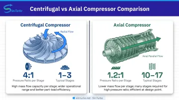
- Centrifugal compressors hit ~4:1 pressure ratio per stage with radial flow, ideal for compact moderate-pressure systems
- Axial compressors average 1.2:1 per stage and need 10–17 stages, but handle extremely high mass flow efficiently
- High-thrust aerospace favors axial designs (smaller frontal area); centrifugals excel in smaller engines and industrial systems
- Pick based on flow rate, pressure ratio, size, flexibility, and maintenance; simulation tools validate configs before hardware
Centrifugal vs Axial Compressors: Quick Comparison
| Feature | Centrifugal | Axial |
|---|---|---|
| Pressure Ratio Per Stage | ~4:1 average (NASA benchmark) | ~1.2:1 average (NASA benchmark) |
| Flow Direction | Radial outward from impeller eye | Parallel to shaft through blade rows |
| Typical Stage Count | 1–3 stages for most applications | 10–17 stages for high-pressure engines |
| Mass Flow Capacity | Moderate; limited by impeller diameter | Very high; smaller frontal area for given flow |
| Operational Range | Wide operating range, more stable at off-design conditions | Narrow range; requires variable inlet guide vanes (VIGVs) for part-load operation |
What is a Centrifugal Compressor?
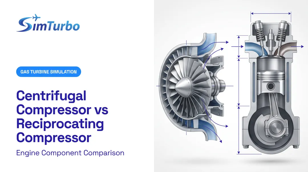
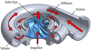
A centrifugal compressor is a dynamic compressor that accelerates gas radially outward through a rotating impeller, then converts kinetic energy to pressure energy in a diffuser. Gas enters near the impeller eye (parallel to the shaft), accelerates outward through impeller vanes, and exits radially into a diffuser or volute where velocity decreases and static pressure rises.
The large radius change from inlet to outlet creates substantial centrifugal acceleration, so each stage can add significant energy. That is why single-stage centrifugal compressors reach high pressure ratios. NASA documents an average single-stage pressure factor of 4.0 for centrifugal compressors, with measured ratios around 4.68:1 in recent rotorcraft research programs.
Packaging is the trade-off. NASA notes that engines using centrifugal compressors tend to have greater cross-sectional area than equivalent axial designs. Efficient multistaging is also harder because flow must return to the axis between stages, which requires complex ducting.
Use Cases and Applications of Centrifugal Compressors
In aerospace, centrifugal stages are common where stage pressure ratio and compactness matter more than the thinnest possible flow path:
- Pratt & Whitney PT6A turboprop/turboshaft: multi-stage axial compressor plus a single-stage centrifugal compressor, with more than 400 million flying hours across 7,500+ operators
- Safran Arriel 2 helicopter turboshaft: axial-plus-centrifugal architecture certified by EASA
- Auxiliary power units (APUs): smaller gas turbines that favor simplicity and reliability over peak performance
The same strengths show up outside flight. Centrifugal compressors are used in moderate-power gas turbines for marine propulsion and in process gas compression in chemical and petrochemical plants.
The Destinus OP16 all-radial gas turbine targets marine and offshore markets, with manufacturer-recommended major overhaul intervals at 42,500 operating hours.
What is an Axial Compressor?
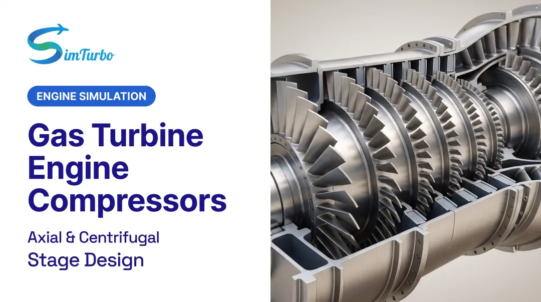
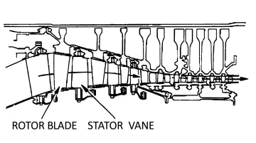
An axial compressor moves gas parallel to the rotation axis through multiple stages of alternating rotating blades (rotors) and stationary blades (stators). Each stage provides incremental pressure rise; typical high-performance axial compressors require 10–17 stages because each stage achieves only modest pressure gain.
Multistage architecture:
NASA illustrates the principle: 8 stages at 1.2:1 per stage yield approximately 4.3:1 overall ratio.
Modern engines multiply this further. The CFM LEAP-1A/-1B uses a 10-stage high-pressure compressor to help achieve a 40–41:1 overall pressure ratio. The GE9X employs 1 fan stage, 3 booster stages, and 11 high-pressure compressor stages for a 60:1 overall pressure ratio and 27:1 core pressure ratio.
Why axial compressors excel at high mass flow:
Flow travels straight through without direction change, allowing large annular flow area with small frontal diameter. This minimizes aircraft drag and achieves high thrust-to-weight ratios, which is critical for commercial and military aviation.
Use Cases and Applications of Axial Compressors
Axial compressors are the standard choice in aerospace propulsion:
- Commercial turbofans: CFM LEAP, GE9X, Rolls-Royce Trent XWB (Trent XWB: 8-stage IP + 6-stage HP; 50:1 OPR)
- Military jet engines: GE's F414 Enhanced Engine uses a 6-stage HPC at about 22,000 lbf and a 9:1 thrust-to-weight class
Power generation:
Large industrial gas turbines use axial compressors for high flow rates and efficiency at design point. The Siemens SGT5-8000H delivers 450 MW(e) simple-cycle output with a 21.0:1 pressure ratio and 935 kg/s exhaust mass flow.
Centrifugal vs Axial: Which Compressor Should You Choose?
The fundamental trade-off:
Centrifugal compressors favor simplicity, a wide operating range, and high pressure per stage. That mix suits moderate overall pressure ratios and variable loads.
Axial compressors favor high mass flow, a smaller frontal area, and very high total pressure ratios. Those traits matter most in high-thrust aerospace work, even with the added complexity.
Flow rate considerations:
If your application needs extremely high mass flow, axial architecture is the practical choice. For moderate flows, centrifugal designs are simpler and more cost-effective. NASA research notes that centrifugal layouts tend to need greater cross-sectional area, while axial stages can be stacked without return-duct complexity.
Pressure ratio requirements:
- Modest overall pressure ratios: 1–2 stage centrifugal designs often suffice
- 15–40:1 ratios (typical high-performance turbofans): multistage axial compressors
- NASA benchmarks: about 4:1 per centrifugal stage vs. 1.2:1 per axial stage on average, though individual test stages have exceeded these figures
Operational envelope:
Engines that must stay efficient across wide speed and load ranges (marine propulsion or variable-demand power generation) benefit from centrifugal compressors' flatter maps and surge resistance. At design point—cruise flight, for example—axial peak efficiency usually outweighs the narrower operating range.
Axial compressors often need variable inlet guide vanes (VIGVs) to hold stall margin at part load. GE's LM6000 VIGVs, for example, close during large power cuts to regulate low-pressure compressor airflow and protect stall margin.
Decision framework:
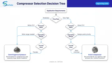
Choose centrifugal when:
- Flow rates are moderate
- Overall pressure ratio is below about 10:1
- Wide operating range is essential
- Simplicity and reliability outweigh peak performance
Choose axial when:
- Mass flow is very high
- Overall pressure ratio exceeds about 15:1
- Frontal area must be minimized (aerospace)
- Design-point efficiency is paramount
Simulating Compressor Performance in Gas Turbine Design
Selecting between centrifugal and axial compressor architectures during preliminary design requires predicting performance (pressure ratio, efficiency, surge margin, and operating range) before expensive hardware prototyping. Traditional methods rely on historical correlations and simplified models that may not capture complex interactions.
How Simulation Supports Comparative Analysis
Engineers can model different compressor configurations inside the same engine architecture. Transient operation, throttle response, and off-design runs make the trade-offs visible before metal is cut.
Component-based platforms let you build the engine from configurable compressor stages, watch performance maps update in real time, and export data for deeper analysis.
SimTurbo's Compressor Modeling Capabilities
SimTurbo's component-based platform supports configurable compressor modeling within complete gas turbine systems. Engineers can:
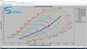
- Analyze compressor maps showing corrected mass flow, pressure ratio, speed lines, and efficiency data
- Monitor real-time operating-point movement during transient simulation
- Overlay compressor maps with engine operating lines to assess surge margin
- Evaluate compressor/turbine matching across altitude, Mach number, and ambient temperature variations
- Export transient data (RPM, EGT, thrust, fuel consumption) to CSV, Excel, MATLAB/Simulink, or Python for post-processing
SimTurbo's J85-GE-21 validation against NASA Lewis Research Center test data achieved accuracy within ±2% for thrust, flow rate, temperature, and thrust-specific fuel consumption.
The platform also models control mechanisms including fuel rate, nozzle area, and variable stator vane control, which is critical for managing compressor operating range in real-world conditions.
Simulation helps engineers compare compressor choices earlier and cut development risk. University students and capstone teams can use SimTurbo's 30-day free trial to test architectures in full engine models before any physical build.
Start your free 30-day trial to evaluate compressor configurations hands-on and accelerate your gas turbine design process.
Conclusion
Centrifugal compressors offer simplicity, wide operating range, and high pressure per stage for moderate-flow applications: industrial gas turbines, marine propulsion, and smaller aerospace engines. Axial compressors provide unmatched mass flow capacity and peak efficiency for high-thrust aerospace applications despite their complexity. The right choice depends on flow, pressure ratio, weight, and efficiency targets for the engine.
Compressor selection directly affects:
- Engine efficiency and fuel consumption
- Weight and thrust-to-weight ratio
- Reliability, surge margin, and maintenance intervals
- Project cost
Running those trade-offs in simulation before hardware commitment helps engineers reduce development risk and reach a sound gas turbine design faster.
Frequently Asked Questions
What is the primary advantage of an axial-flow compressor over a centrifugal compressor?
Axial compressors handle much higher mass flow rates with smaller frontal area, making them essential for high-thrust aerospace applications where minimizing drag is critical. Flow travels parallel to the shaft without direction change, allowing efficient packaging in turbofan engines.
How many stages do axial compressors typically require compared to centrifugal compressors?
Axial compressors typically need 10–17 stages to achieve pressure ratios that centrifugal compressors accomplish in 1–3 stages. NASA documents average single-stage pressure factors of ~1.2:1 for axial vs. ~4:1 for centrifugal compressors, requiring stage multiplication to reach high overall ratios.
Why do modern jet engines use axial compressors instead of centrifugal compressors?
High-thrust turbofan engines require very high mass flow rates and overall pressure ratios (20–60:1), which axial compressors deliver more efficiently with smaller frontal area despite their complexity. Examples include the CFM LEAP (10-stage HPC, 40:1 OPR) and GE9X (11-stage HPC, 60:1 OPR).
What is compressor surge and why does it matter in compressor selection?
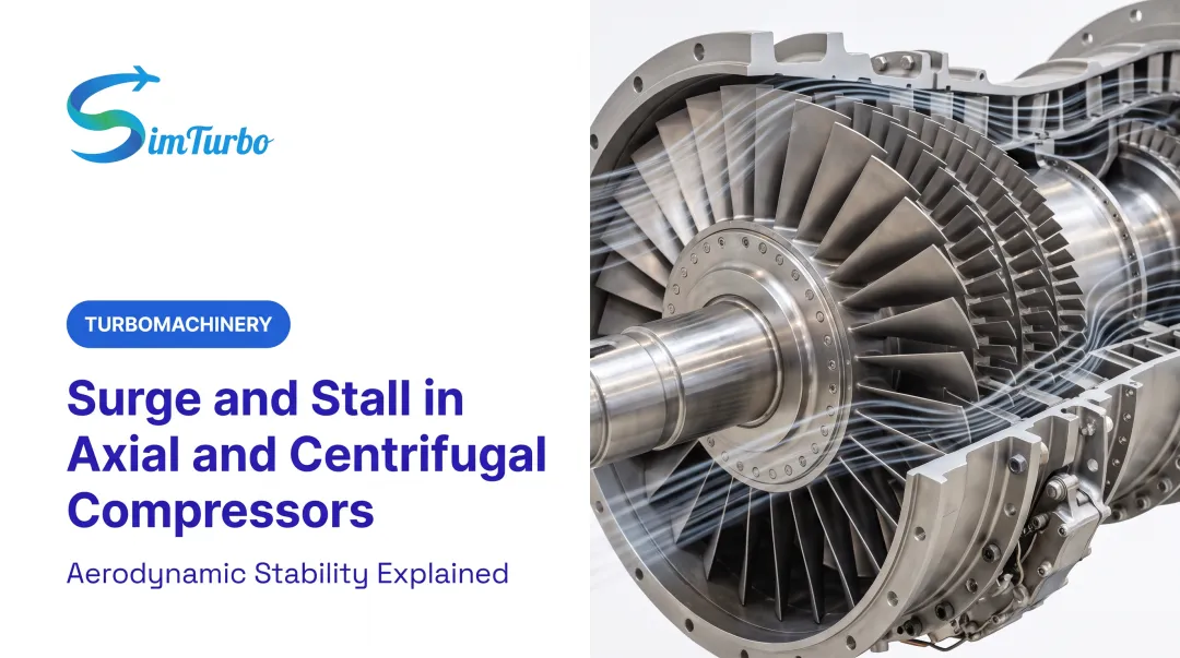
Surge is a damaging flow instability in which compressor flow can reverse at low flow rates. Axial machines often need variable inlet guide vanes (VIGVs) to protect stall margin at part load, while centrifugal compressors typically offer a wider stable operating range.
Can centrifugal compressors be used in gas turbine engines?
Yes. Smaller gas turbines such as the PT6A turboprop, APUs, early turbojets, and Arriel 2 helicopter engines use centrifugal compressors for simplicity, reliability, and wide operating range. The PT6A family has accumulated more than 400 million flying hours.
Which compressor type is more efficient for gas turbine applications?
Measured efficiency depends on test conditions and component configuration. NASA's centrifugal research stage achieved 85.5% polytropic efficiency, while a transonic axial test stage reached 83.1% peak efficiency. Both types can deliver strong efficiency at design point; centrifugal compressors maintain better efficiency across wider operating ranges.