Many operators struggle with drift. After an outage, a hardware swap, or a seasonal ambient shift, a Dry Low NOx (DLN) combustor can quietly slide out of its tuned setpoint. The result: compliance violations, hardware wear, or unplanned trips. EPA data shows just how much is at stake — dry lean-premixed control can cut NOx to 9-42 ppmv, versus 99-430 ppmv for uncontrolled systems (EPA).
This article covers what combustion tuning actually changes, why DLN systems are especially sensitive to it, the parameters engineers track, common failure modes, and how simulation platforms let engineers and students study tuning behavior before touching live hardware.
Key Takeaways
- Combustion tuning changes fuel splits and control constants in software, not hardware
- DLN combustors react more to airflow variability across cans than to fuel flow
- Pressure oscillations need direct measurement; emissions data alone won't show them
- DLN-1 and DLN-2.6 fail differently and need frame-specific tuning
- Simulation platforms model combustor and control response before live parameter changes
What Is Gas Turbine Combustion Tuning
Combustion tuning means adjusting fuel splits between nozzle circuits, total fuel flow, and control constants like temperature-control curves. The goal: balance NOx, CO, combustion dynamics, and lean blowout margin across the unit's operating range.
In practice, that means managing an operability window:
- Richer mixtures push NOx up
- Leaner mixtures raise CO, dynamics, and blowout risk
- The right tune holds margin on both sides across load, ambient, and fuel conditions
Tuning happens through the control system itself. No one opens the machine to do it. It's typically required at:
- Initial commissioning
- After hardware replacement
- Following major outages
- When fuel composition or seasonal conditions shift materially
A Real-World Example: OEM Auto-Tuning Results
GE's Autonomous Tuning system for aeroderivative DLE units adjusts fuel splits and flame-temperature targets every two seconds. Reported results: up to 14% lower CO and 12% lower NOx, depending on fuel gravity. One European LM6000 site cut NOx by 10% and avoided a proposed $2 million, 12-week overhaul (GE Vernova).
Done well, that kind of tuning buys operators compliance margin and avoided capital spend.
Why Dry-Low-NOx (DLN) Combustion Systems Require Tuning
DLN combustors premix fuel and air before combustion, lowering flame temperature and cutting NOx by roughly an order of magnitude compared to diffusion combustors. The trade-off is reduced flame stability, and that instability is exactly why tuning matters so much for DLN units.
Here's the underlying problem: fuel flow is relatively easy to control precisely. Airflow is not. Manufacturing tolerances across liners, caps, and transition pieces create can-to-can airflow variation that fuel control alone can't fully correct. Every time hardware gets reassembled after an outage, that variation resets.
DLN-1 vs. DLN-2.6: Different Failure Modes
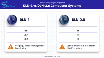
These two combustor families don't fail the same way, and tuning approaches reflect that:
| Combustor Type | Common Frames | Primary Risk |
|---|---|---|
| DLN-1 | 6B, 7EA, 9EA, early 7FA/9FA | Staging and mode-management sensitivity during premix transitions |
| DLN-2/2.6 | 6F, 7F, 9F | Lean blowout and NOx excursions at turndown, particularly in cold weather |
DLN-2.6 systems on 7FA units, for example, have demonstrated below 9 ppm NOx and CO across 50-100% load on natural gas (ASME). Newer DLN 2.6e systems on 7HA.03 units push down to 5 ppm NOx at 15% O2 — right at the edge of lean blowout (ASME). That's the operability window in action: lower emissions, thinner margin.
Instrumentation matters too. Ambient pressure and temperature sensors, fuel pressure transducers, and dynamic-pressure probes all feed the tuning process. Drift in any of these can look like a combustion problem when it's actually a sensor problem (a common, underappreciated root cause of apparent tuning issues).
Key Parameters and Combustion Dynamics Monitored During Tuning
A tuning engineer isn't watching one number. They're tracking a set of interlocking parameters:
- Fuel and air flow — total flow, staged splits, fuel pressure, gas-supply pressure
- Exhaust temperature spread — can-to-can thermal uniformity
- Emissions — NOx and CO concentrations
- Combustion dynamics — acoustic pressure oscillations inside the combustor
Why Dynamics Get Measured Separately
Combustion dynamics don't show up in emissions readouts. They're acoustic pressure pulsations that can degrade or destroy hot-section hardware even while NOx and CO look perfectly normal.
At one documented plant, pulsations as low as 0.4 psig at roughly 2,400–2,500 Hz caused hardware damage. Lowering alarm limits and retuning restored reliable operation (Power Engineering).
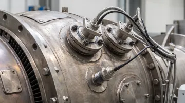
Monitoring setups vary by need. Portable systems support periodic, often seasonal tuning checks by OEM field engineers. Permanent systems continuously trend dynamic pressure and alarm on developing problems, which suits cycling units and narrow-margin combustors.
Beyond passive monitoring, OEM closed-loop tools fold dynamics feedback into automated control. GE's OpFlex AutoTune checks combustion settings 25 times per second, with over 10 million hours of fleet operation across 800+ systems (GE Vernova).
How Simulation Tools Support Combustion Tuning Education and Analysis
Before anyone touches a live control parameter, there's real value in modeling combustor and control-loop behavior first. That's where a platform like SimTurbo comes in.
SimTurbo is a Windows-based, component-based gas turbine simulation environment. Engineers build models from inlets, compressors, combustors, turbines, and control elements (including PID controllers and limiters) and run them in real time.
What This Looks Like in Practice
- Transient and steady-state modeling — visualize how throttle changes and fuel-air adjustments ripple through the system
- Real-time PID behavior — speed/RPM, temperature, and surge-margin control loops respond to setpoint changes the way they would on live hardware
- Data export — output CSV and Excel files with time-series data (RPM, EGT, thrust, SFC) for further work in MATLAB, Simulink, or Python
SimTurbo's steady-state model has been validated against NASA Lewis J85-GE-21 test data, matching thrust, flow rate, temperature, and TSFC within ±2%. That fidelity supports clear cause-and-effect analysis of control response.
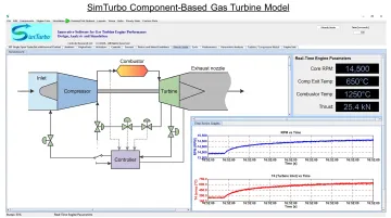
SimTurbo's combustor components are generic and configurable rather than pre-built DLN-1 or DLN-2.6 multi-can models. The tool is built for fundamental combustor-control interaction (heat addition, fuel scheduling, closed-loop response), not for replicating a specific OEM's can geometry.
For university capstone teams, control system engineers, or researchers who need a low-risk way to prototype tuning logic before it ever touches a real machine, SimTurbo offers a 30-day free trial and discounted university/lab licensing.
Common Tuning Challenges and Best Practices
A handful of issues account for most tuning problems in the field:
- Fuel nozzle imbalance — DLN nozzles have smaller passages than diffusion nozzles, so particulate plugging, coking, damaged seals, or blocked air paths shift local fuel-air ratio and can trigger dynamics.
- Instrumentation drift — miscalibrated pressure or temperature sensors can mimic a combustion problem.
- Mode-transition instability — the shift between premix stages during turndown is a common point of instability.
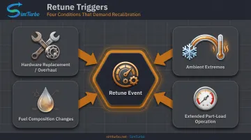
Retune on events, not a fixed calendar. Trigger a retune after:
- Any combustion hardware replacement or major overhaul
- Ambient extremes (especially cold-weather swings that push DLN-2.6 systems toward blowout)
- Fuel composition changes
- Extended part-load operation
Treat dynamics monitoring as an ongoing discipline after commissioning. Trending sensor health and reviewing control-system data regularly catches drift before it becomes a compliance issue or a hardware failure.
Frequently Asked Questions
How do you control gas turbine speed?
Speed and load are governed by fuel-flow control loops, typically PID-based, that respond to demand signals. Combustion tuning works alongside this to keep the fuel-air ratio within safe, compliant limits at each operating point.
How often do gas turbines need maintenance?
Intervals depend on operating hours, load cycling, and OEM recommendations rather than a fixed calendar. GE's DLN 2.6 combustion systems, for instance, support inspection intervals up to 24,000 factored fired hours or 900 starts, with tuning checks tied to outage schedules.
What is the start sequence for a gas turbine?
The general sequence runs purge, ignition, warm-up, acceleration to idle, then loading. Combustion mode transitions during this sequence are a key area where tuning stability directly affects reliable startup.
What is meant by "tuning" a DLN system?
Tuning means adjusting fuel splits and control constants through the turbine's control system to keep NOx, CO, dynamics, and lean blowout margin within acceptable limits. No hardware changes are involved.
Why do DLN combustion systems require tuning after maintenance?
Reassembled hardware introduces can-to-can airflow variation from manufacturing tolerances and reassembly differences. Fuel split adjustments correct for that variation and restore the tuned baseline.