Blade design varies enormously depending on where in the engine you look. A blade sitting right behind the combustor faces conditions that would melt a blade three stages downstream. This article breaks down the major turbine blade types, how they differ, and how engineers actually choose between them.
TL;DR
- Blades are classified by stage (high-pressure vs. low-pressure) and function (rotor vs. stator/nozzle)
- Thermal tolerance, aerodynamic efficiency, and mechanical stress trade off differently for each type
- Materials and cooling design—alloys, coatings, and internal channels—set one blade type apart from another
- Choose by temperature, pressure ratio, application, and budget—not by “most advanced” alone
- Simulation lets engineers compare stage configurations and trade-offs before manufacturing
What Are Turbine Blades?
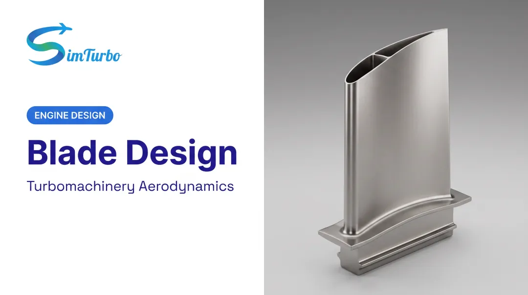
A turbine blade is an airfoil-shaped component that extracts energy from high-velocity, high-temperature gas or steam flow, converting it into shaft rotation. In a gas turbine or jet engine, blades sit immediately downstream of the combustor, in the turbine section proper.
NASA describes the turbine's job simply: it extracts energy from hot gas exiting the combustor and uses that energy to drive the compressor and fan through connected shafts. The concept is simple; the engineering is not.
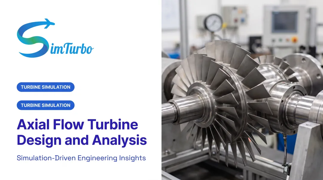
Each turbine stage typically pairs a stationary nozzle or stator row with a rotating blade row:
- Stator — directs and accelerates flow into the rotor
- Rotor — captures that flow and converts it into shaft torque
Because pressure drops progressively through the turbine, blade geometry, material choice, and cooling strategy must be engineered stage by stage, not applied uniformly across the whole machine.
Turbine blades aren't generic parts you swap in and out. Their design directly determines how efficient an engine is and how long it lasts before an overhaul.
Why Do Turbine Blade Types Matter?
Here's the core problem: gas temperature at combustor exit can reach 2,000 K (1,700°C), according to Rolls-Royce. That is several hundred degrees above the melting point of the alloys used to build the blades themselves.
NASA's own benchmark for modern turbine inlet temperatures sits at 1,800–2,000 K, with blade metal typically running at 1,040–1,090°C.
That gap between gas temperature and metal temperature is why blade type isn't a cosmetic choice. Using the wrong design or material for a given stage leads to:
- Efficiency loss from suboptimal cooling flow or aerodynamic mismatch
- Premature creep: slow permanent deformation under sustained heat and stress
- Thermal fatigue from repeated heating and cooling cycles
- Catastrophic failure in the worst cases
One documented failure case saw a blade crack after 20,000 hours at 700–850°C, driven by combined creep and fatigue. Even "moderate" temperature stages aren't immune.
Modern engineering teams test these trade-offs virtually before cutting metal. At SimTurbo, engineers can model compressor, turbine, and nozzle behavior, including corrected mass flow, pressure ratios, and component efficiencies, before committing to a physical build.
That doesn't replace detailed blade-level aerodynamic design. It does help validate how a given stage configuration performs across the engine cycle before expensive prototyping starts.
Types of Turbine Blades
Turbine blades are typically classified two ways: by stage (which pressure/temperature zone they occupy) and by function (whether they rotate or stay fixed). Each classification addresses a different engineering demand.
High-Pressure (HP) Turbine Blades
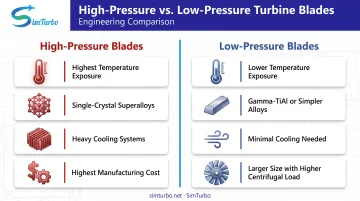
HP blades sit immediately downstream of the combustor. They face the highest gas temperatures and pressures anywhere in the engine.
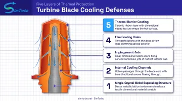
How they survive: HP blades rely on a layered defense system:
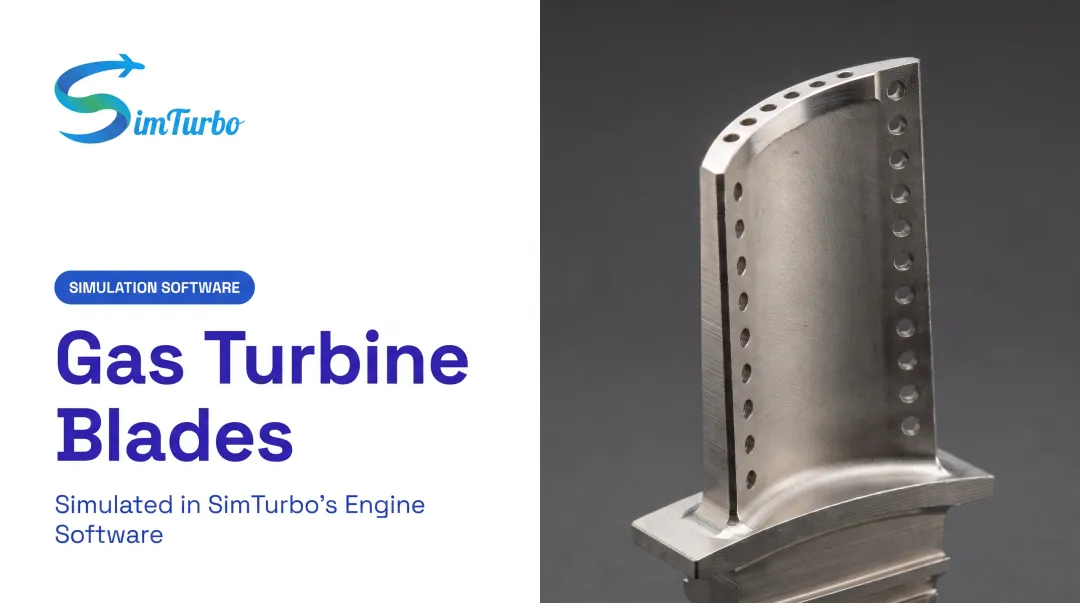
- Internal cooling channels that route compressor bleed air through the blade core
- Impingement jets targeting high-heat zones like the leading edge
- Film cooling, where bleed air exits through surface holes to form a protective cool layer
- Thermal barrier coatings (ceramic layers with low thermal conductivity)
- Single-crystal nickel superalloys, which eliminate grain boundaries and improve creep resistance
What makes them different: HP blades carry the highest thermal load and the most advanced cooling/material requirements of any turbine stage.
Best suited for: Modern jet engines and advanced power-generation turbines where maximizing turbine entry temperature translates directly into better thermodynamic efficiency.
The trade-off: All that sophistication costs money. Single-crystal casting, multi-layer coatings, and precision-drilled cooling holes make HP blades the most expensive and complex to manufacture. A peer-reviewed study documented one set of 40 single-crystal blades priced above $600,000, with production lead times of 60–90 weeks. That's one documented example, not a universal price tag, but it illustrates the scale of investment HP hardware demands.
Low-Pressure (LP) / Intermediate-Pressure Turbine Blades
Further downstream, gas has expanded and cooled considerably. LP blades extract the remaining energy to drive fans or compressors.
Why they're different: Lower temperatures mean LP blades can often skip heavy cooling systems entirely, or use much simpler cooling than HP blades require. But that doesn't mean they're easy to design.
The real challenge is mechanical, not thermal:
- LP blades are physically larger, often much longer than HP blades
- Longer blades mean higher centrifugal loads — Rolls-Royce has compared the centrifugal force on a spinning blade to "a London bus hanging from each blade"
- Vibration and fatigue become bigger concerns as blade length increases
Material choices reflect this shift. A 2018 materials review associates lightweight gamma-TiAl alloys with LP applications in the 600–900°C range, and GE uses titanium aluminide in the GEnx engine's LPT stages 6 and 7. Lower density helps offset the centrifugal stress that comes with longer blades, but oxidation resistance, fatigue behavior, and casting quality still need validation for each specific application.
Best suited for: Turbofan fan drives, industrial power turbines, and any stage where cost efficiency matters more than squeezing out marginal thermal gains.
Limitations: LP blades contribute less to overall thermal efficiency than HP blades do, and their larger size introduces its own set of vibration and fatigue challenges that HP blades don't face in the same way.
Rotor Blades vs. Stator (Nozzle) Blades
This is a different axis of classification entirely: motion and function, not temperature zone.
| Attribute | Rotor Blade | Stator/Nozzle Blade |
|---|---|---|
| Motion | Rotates with the shaft | Fixed in place |
| Primary job | Converts flow energy into mechanical torque | Directs and accelerates flow onto the next rotor row |
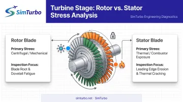
| Main stress | Centrifugal pull plus bending, vibration, thermal fatigue | Pressure and thermal stress, no centrifugal tensile load |
| First-stage exposure | Behind the first nozzle | Can face direct combustor discharge |
Every turbine stage needs both a rotor row and a stator row working together, alternating to extract energy efficiently. NASA defines rotor blades as the shaft-connected rotating components, and stators as the fixed rows that redirect flow.
It's a common misconception that stators are "lightly loaded" simply because they don't spin. That's wrong. ASME research identifies the nozzle guide vane as the first component to face direct combustor discharge, and documents thermal-fatigue failures in service.
A stator blade can face hotter gas than the rotor immediately behind it, without any benefit from the mechanical cooling effects some rotor geometries provide.
Where this distinction matters most: maintenance planning and blade-specific design optimization. Rotor blade inspections focus heavily on centrifugal fatigue and creep; stator inspections focus more on thermal-fatigue cracking.
How to Choose the Right Turbine Blade Type
Choose blades by matching them to actual operating conditions, not by defaulting to the most advanced HP-style design for every application.
Key factors to weigh:
- Operating temperature and pressure ratio of the specific stage you're designing for
- Application type — aerospace, marine propulsion, power generation, or research/education
- Required efficiency gains versus what you can justify spending on manufacturing and upkeep
- Material and cooling complexity your design and budget can actually support
- Durability needs and maintenance intervals over the engine's service life
Engine architecture also shapes these decisions. Dual-spool configurations, where high-pressure and low-pressure spools interact independently, create distinct HP and LP stage environments that need separate design treatment. That differs from a single-spool layout, where the turbine section is more uniform.
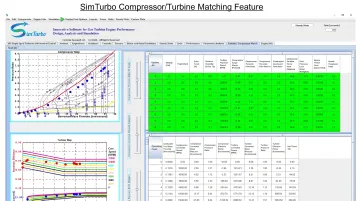
Simulation helps sort those architecture tradeoffs before hardware is locked in. SimTurbo's platform supports both single-spool and dual-spool turbojet modeling, so engineers can examine compressor and turbine matching, pressure ratios, and component efficiencies across different architectures.
The platform's J85-GE-21 validation against NASA Lewis Research Center test data showed accuracy within ±2% for thrust, mass flow, temperature, and fuel consumption. That gives engineers and students solid groundwork for modeling stage-level behavior before committing to hardware. Simulation data can also be exported to Excel, MATLAB/Simulink, or Python for deeper post-processing.
What to Check Before Finalizing a Turbine Blade Type
Before you lock in a blade type, run through this checklist:
- Don't over-specify. Applying HP-style cooling and exotic materials to a stage that doesn't need them adds cost without adding value.
- Weigh the full trade-off. Cost, weight, and manufacturing complexity matter just as much as peak performance numbers.
- Plan for the long haul. Maintenance access, repair intervals, and part availability affect total lifecycle cost more than initial performance specs do.
- Don't default to familiarity. Past engine heritage is not a substitute for matching the blade to actual operating conditions.
Conclusion
Turbine blades do the real work of energy conversion across aerospace, marine, and power-generation systems. There's no single best blade design: HP, LP, rotor, and stator blades each solve a different mix of thermal, mechanical, and functional demands.
Understanding those differences—and how they interact with engine architecture, materials, and cooling strategy—separates a reliable design from one prone to premature failure. Whether you're a student learning the basics or an engineer running trade studies on a new architecture, that insight pays off long before metal gets cut.
SimTurbo lets you explore those architecture, materials, and cooling trade-offs in real-time simulation so students and engineers can test options before committing to hardware.
Frequently Asked Questions
What are the three types of turbine blades?
The three stage types are high-pressure (HP), intermediate-pressure (IP), and low-pressure (LP) blades. Blades are also grouped by function as rotating blades (rotors) or stationary vanes (stators/nozzles).
How much does one jet turbine blade cost?
Costs vary widely by material, stage, and manufacturing process. One documented example cites over $600,000 for a set of 40 single-crystal HP blades, with 60–90 weeks of production time; LP blades using simpler alloys generally cost less.
Why are turbine blades so hard to make?
They need nickel superalloys, single-crystal casting, internal cooling passages, and tight tolerances. Those features must hold up under extreme heat and centrifugal load at the same time.
What are the key differences between high-pressure and low-pressure turbines?
HP blades face higher temperatures and require advanced cooling and single-crystal materials. LP blades run cooler but are larger, facing higher centrifugal and vibration loads with simpler materials.
What materials are turbine blades typically made from?
Nickel-based superalloys dominate, especially single-crystal variants for HP stages. Some LP stages use gamma-TiAl for weight savings, and ceramic matrix composites are emerging for select hot and lightweight applications.
How are turbine blades cooled?
Cooling methods include internal convection, impingement jets, film cooling, and transpiration through porous walls. HP blades usually combine several of these; LP blades often need little or no cooling.