Simulation has become the answer. By modeling the thermodynamic and aerodynamic processes inside turbojet engines using computational methods, engineers can design, test, and refine engines entirely in software before cutting the first piece of metal. This article explores the fundamentals of turbojet simulation, the methodologies available, validation practices, and real-world applications across aerospace design, control system development, and engineering education.
Key Takeaways
- Turbojet simulation spans simplified physics-based models through high-fidelity CFD
- Component-based models expose inlet–compressor–combustor–turbine–nozzle interactions instead of a black box
- Validate models against experimental data (e.g., NASA J85 tests) to keep simulation accuracy trustworthy
- Match fidelity to the job: 0-D for controls, 1-D for preliminary design, CFD for component detail
- Modern tools support real-time analysis, control prototyping, and teaching without expensive hardware
Understanding Turbojet Engine Fundamentals
Basic Operating Principle and Engine Types
A turbojet compresses incoming air, mixes it with fuel, burns the mixture, extracts enough turbine work to drive the compressor, and converts the remaining gas energy into a high-speed exhaust jet that produces thrust. This simple sequence defines the turbojet's operation: intake, compression, combustion, expansion, and exhaust.
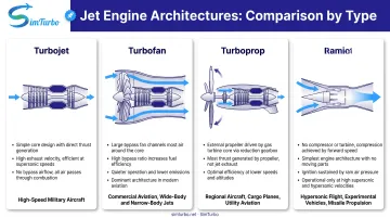
Turbojets differ from related engine types in configuration and application:
- Turbofan: Extracts additional turbine work to drive a large fan, bypassing most air around the core for higher efficiency at subsonic speeds
- Turboprop: Extracts even more shaft power to drive a propeller, optimized for lower-speed flight
- Ramjet: Contains no compressor or turbine, relying entirely on vehicle speed to compress incoming air
Each configuration suits a different mission profile. Turbojets still matter for high-speed military aircraft and any application where simplicity and thrust-to-weight ratio come first—and they remain the core architecture most jet-engine simulations build on first.
The Brayton Cycle and Governing Equations
The Brayton cycle provides the theoretical foundation for turbojet operation. The ideal cycle consists of:
- Isentropic compression (no entropy increase)
- Constant-pressure heat addition (combustion)
- Isentropic turbine expansion
- Constant-pressure heat rejection (exhaust)
The ideal thermal efficiency depends on pressure ratio: η = 1 - 1/rp^((γ-1)/γ), where rp is the pressure ratio and γ is the specific heat ratio. Real engines deviate from this ideal due to friction, heat transfer, incomplete combustion, and turbulence, but the Brayton cycle remains the analytical baseline.
Simulation must solve fundamental conservation equations:
- Mass conservation: Flow entering each component equals flow exiting (accounting for fuel addition and bleed extraction)
- Energy conservation: Enthalpy changes balance with work extraction/addition and heat transfer
- Momentum conservation: Pressure forces, shear stresses, and body forces govern flow acceleration
- Equation of state: Relates pressure, temperature, and density for the working fluid
Those balance laws still sit on top of real gas-path physics. Accurate simulation must also capture:
- Compressibility and shocks: Supersonic flow in inlets and nozzles produces shock waves with associated pressure losses
- Turbulence: Affects mixing, heat transfer, and losses throughout the engine
- Boundary layers: Growth, separation, and reattachment influence component efficiency and operability
- Combustion: Fuel-air mixing, flame stabilization, chemical kinetics, and heat release
- Heat transfer: Convection and radiation govern component temperatures and cooling requirements
Critical Performance Metrics and Off-Design Operation
Engineers track a short set of parameters when they judge turbojet performance.
Thrust is the net force produced. Gross thrust comes from exhaust momentum and pressure, reduced by ram drag from decelerating inlet air:
Fnet = (ṁair + ṁfuel)Ve - ṁairV0 + (Pe - P0)Ae
where ṁ is mass flow, Ve is exhaust velocity, V0 is flight velocity, Pe is exit pressure, P0 is ambient pressure, and Ae is exit area.
Other primary metrics include:
- TSFC: Fuel mass flow per unit net thrust; lower is better, but only at a stated operating point
- Overall pressure ratio: Compressor-exit total pressure divided by compressor-inlet total pressure
- Corrected speed and flow: Nc = N/√θ and Wc = W√θ/δ, with θ = Tt/Tref and δ = Pt/Pref, so maps stay comparable across ambient conditions
Flight condition shifts those same metrics. Thrust generally falls with altitude as density and mass flow drop, though ram recovery can raise thrust at higher Mach. Hotter ambient air cuts maximum thrust by lowering density and raising compressor inlet temperature.
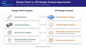
Design-point analysis sets the cycle and component sizing for one condition, typically maximum thrust at sea level.
Off-design analysis then predicts behavior at other thrust settings, altitudes, and Mach numbers once component maps are fixed. Simulation has to cover both regimes—real engines spend most of their life off the design point.
Key Components of Turbojet Simulation
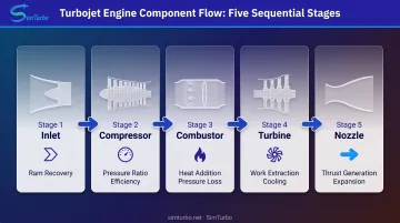
Turbojet simulation is built block by block, from inlet to nozzle. Each component needs a fidelity level that matches the question you are answering: cycle matching, off-design maps, or transient response.
Inlet Modeling and Ram Pressure Recovery
The inlet decelerates incoming air and converts kinetic energy to pressure rise. Ram pressure recovery sets compressor-face pressure and, with it, available thrust. Higher recovery yields more pressure at the compressor face and higher thrust.
Subsonic inlets are relatively simple, with smooth deceleration and minimal losses. Supersonic inlets require careful shock management. NASA research on supersonic inlets defines recovery as the engine-face to freestream total-pressure ratio, a critical design metric for high-speed flight.
Simulation must account for:
- Mach number-dependent pressure recovery
- Boundary-layer growth and separation risk
- Shock structure and shock/boundary-layer interaction in supersonic designs
- Distortion patterns that can destabilize the compressor
Compressor Simulation Approaches
The compressor provides the pressure ratio that drives cycle efficiency. Simulation methods range from lumped models to detailed stage-by-stage analysis.
Component maps correlate corrected speed and corrected mass flow with pressure ratio and efficiency. These empirical maps come from rig testing and capture real compressor behavior including operating limits. At each timestep, the simulation interpolates the map to find the current operating point.
Map data must state which efficiency definition it uses:
- Isentropic efficiency compares actual compression work to ideal isentropic work for the same pressure ratio
- Polytropic efficiency treats compression as a series of infinitesimal steps and is less sensitive to pressure ratio
The two are not interchangeable without conversion.
Off-design behavior depends heavily on map quality. NASA's J85 modeling study matched design point closely, but generic compressor maps diverged at off-design speeds. Without an actual turbine map, off-design turbine error also stayed unknown. Maps must cover the full operating envelope, or predictions lose reliability.
Combustor Modeling Techniques
The combustor adds energy to the flow by burning fuel. Modeling approaches depend on the required fidelity:
Low-order models assume complete combustion, apply fuel lower heating value, solve mass and enthalpy balances, and model pressure loss. NASA's J85 example used a typical burner pressure-loss range of 1-5% for thermodynamic cycle calculations.
High-fidelity CFD resolves fuel injection, droplet evaporation, turbulent mixing, finite-rate chemistry, flame stabilization, liner cooling, and emissions formation. NASA's 2020 lean direct injection study investigated CFD prediction of CO and soot under lean direct injection conditions.
The outlet temperature distribution (pattern factor) affects turbine life and performance. Choose combustor fidelity based on whether you need cycle heat release, emissions, or liner durability detail.
Turbine Performance Representation
The turbine extracts work to drive the compressor and accessories. As with the compressor, maps relate pressure ratio, corrected flow, corrected speed, and efficiency.
Cooling air complicates turbine modeling. Bleed air mixed into the turbine reduces gas temperature but adds mass flow and changes velocity triangles. NASA's modeling guidance notes that simple mass-weighted enthalpy mixing is sufficient only for low relative cooling flow; higher cooling rates require more detailed mixing models.
Thermal limits constrain operation. Gas temperature may exceed allowable metal temperatures by hundreds of degrees, making cooling design and temperature prediction essential for safety and durability.
The steady-state shaft-work balance is fundamental: turbine power must equal compressor power plus accessory loads and losses. This matching condition determines the engine's operating point during off-design simulation.
Nozzle Flow and Thrust Calculation
The nozzle accelerates exhaust gas and produces thrust. Converging nozzles reach Mach 1 at the throat and then choke, so mass flow cannot increase further. Converging-diverging nozzles allow supersonic acceleration beyond the throat when higher pressure ratios justify the weight and complexity.
Thrust calculation combines momentum flux and pressure thrust:
Gross thrust = ṁ_exit × V_exit + (P_exit − P_ambient) × A_exit
Subtracting ram drag (inlet momentum) gives net thrust. NASA's J85 model applied a thrust coefficient for friction, flow angularity, non-ideal expansion, leakage, and cooling-air throttling losses. Those corrections separate real engine thrust from ideal one-dimensional results.
CFD can resolve internal shocks, over/underexpansion, separation, plume mixing, and installation effects. For system-level performance, thrust-coefficient corrections on one-dimensional flow models usually deliver enough accuracy at far lower cost.
Simulation Methodologies and Approaches
Zero-Dimensional Thermodynamic Models
Zero-dimensional (0D) models treat each component as a control volume with inlet and outlet states. Station properties (pressure, temperature, flow) are solved from algebraic mass, energy, momentum, and shaft-work balances plus component maps.
Advantages:
- Fast computation: sweeps and transients run in seconds
- Suitable for control system development and real-time simulation
- Effective for whole-engine performance prediction and design-point/off-design analysis
Limitations:
- No spatial resolution inside components
- Accuracy depends on quality of empirical component maps
- Unreliable when operating outside map calibration regions
Dynamic 0D models add shaft inertia, volumes, actuators, sensors, fuel systems, and controller states. That extra dynamics layer supports transient simulation of acceleration, deceleration, and control response.
One-Dimensional Meanline Models
One-dimensional (1D) models add axial resolution by dividing components into multiple stations or stages. Property variations (pressure, temperature, velocity) are calculated from inlet to exit using conservation laws and empirical loss correlations.
NASA's Object-Oriented Turbomachinery Analysis Code performs compressor and turbine meanline and streamline analysis, computing row-by-row velocity triangles, incidence, loss, and choking.
Between full-engine 0D models and 3D CFD, 1D meanline methods are a practical middle layer. They cost far less than CFD while still capturing axial flow structure, and they support:
- Preliminary stage design and matching
- Operability studies, including surge propagation
- Row-by-row loss and choking checks before committing to 3D runs
Empirical deviation and loss correlations remain a limitation when flows show strong separation or three-dimensional effects.
Computational Fluid Dynamics Approaches
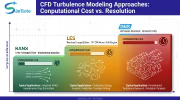
RANS (Reynolds-Averaged Navier-Stokes) solves time-averaged flow equations with turbulence modeled. It is the engineering baseline for inlet, blade-row, combustor, and nozzle design.
LES (Large Eddy Simulation) resolves large unsteady eddies while modeling subgrid scales. NASA characterizes LES as a compromise between DNS and RANS, justified for combustor mixing, large separation, and shock-induced unsteadiness when transient detail changes design decisions. Fine grids, small timesteps, and long sampling windows make LES expensive. NASA's 2021 propulsion grand-challenge report puts high-fidelity full-engine LES on the order of 10^7 CPU-hours.
DNS (Direct Numerical Simulation) resolves all turbulence scales without modeling. NASA describes DNS as extremely expensive and mainly a research method at engine Reynolds numbers.
Reach for CFD when you need local detail 0D/1D cannot provide: aerodynamic losses, separation zones, temperature hot spots, or combustion instabilities. For system-level performance and control work, 0D and 1D models remain the practical choice.
Real-Time Simulation Capabilities
Real-time means every model update completes within its assigned simulation interval. This requires:
- Zero-dimensional component models with shaft dynamics
- Pretabulated maps and thermochemistry
- Fixed-step solvers
- Multirate partitions for fast (sensors, actuators) and slow (thermal) states
A 2011 peer-reviewed study used multi-rate hardware-in-the-loop simulation to test a turbojet fuel controller, confirming real-time feasibility for control development.
Real-time simulation supports:
- Control-law prototyping before hardware exists
- Hardware-in-the-loop testing with physical controllers
- Pilot training simulators
- Academic laboratory demonstrations
Speed comes at the cost of spatial detail, but for control and operability studies, real-time capability often outweighs CFD fidelity.
Simulation Software and Tools
Commercial CFD Platforms for Detailed Component Analysis
ANSYS Fluent provides integrated meshing, turbulence models, reacting-flow chemistry, and multiphase capability. Pratt & Whitney published its incorporation of Fluent into CFD-based combustor design, demonstrating industry acceptance. Fluent documentation outlines best practices for gas-turbine combustion meshing.
Simcenter STAR-CCM+ offers automated workflow, GPU acceleration, and reacting-flow chemistry combined with multiphase capability. 2026 GPU-accelerated turbomachinery documentation highlights performance improvements for large-scale simulations.
OpenFOAM is an open-source CFD platform with compressible, multispecies, multiphase combustion solvers. It provides source access and customization but requires stronger in-house verification and workflow ownership.
Typical CFD workflow:
- Geometry definition and domain setup
- Mesh generation with resolution studies for boundary layers, shocks, and flames
- Material properties, chemistry, turbulence, and combustion model selection
- Boundary conditions and rotating-interface setup
- Convergence and conservation checks
- Grid, timestep, and model sensitivity studies
- Post-processing and validation against experimental data
CFD excels at component-level aerodynamic design but demands HPC resources, extended run times, and specialized expertise.
Real-Time and Component-Based Simulation Platforms
When the goal is system-level performance, control design, or classroom demonstration—not blade-resolved aerodynamics—component-based real-time platforms are usually the better fit. They trade spatial detail for speed, interactivity, and full-engine transient behavior on a standard PC.
SimTurbo is a Windows-based platform for real-time gas turbine performance simulation, control design, and education. Its drag-and-drop architecture lets engineers assemble turbojet models from reusable blocks:
- Engine path: inlet, compressor, combustor, turbine, nozzle, and shaft
- Controls: PID controllers, limiters, actuators, and sensors
- Optional hardware: recuperators, intercoolers, and similar cycle add-ons
Blocks stay visible, movable, and editable, so Brayton-cycle and mass-flow effects show up as you reconnect the flow path—not as a sealed black-box model.
The solver includes real-gas effects, standard thermodynamic relations, component maps, and pressure-loss models. Live outputs cover:
- Real-time graphs and transient parameter displays
- Compressor and turbine maps
- T-S and P-V cycle diagrams
- Performance tables
SimTurbo's J85-GE-21 single-spool turbojet model matched NASA Lewis Research Center test data to within ±2% on thrust, flow rate, temperature, and thrust-specific fuel consumption. It supports steady-state and transient runs, including startup, throttle changes, stall/surge events, and control-system response.
SimTurbo offers:
- 30-day free trial with full product features
- Monthly subscription at $59.99/month
- One-year license at $599
- Lifetime license at $5,999 with free upgrades, maintenance, and technical support
- University student discounts and classroom/lab programs for engineering education
It runs on standard Windows PCs with at least 8 GB RAM and a modern multi-core processor. A dedicated graphics card and SSD are recommended for smoother real-time displays. Data exports to CSV, Excel, MATLAB/Simulink, and Python for post-processing and external control-law checks.
Selecting the Right Tool for Your Objectives
Match simulation tool to engineering goal:
| Objective | Recommended Approach |
|---|---|
| Detailed component aerodynamic design | RANS CFD (Fluent, STAR-CCM+, OpenFOAM) |
| System-level performance and cycle optimization | 0D thermodynamic models |
| Control system development and HIL testing | Real-time 0D dynamic simulation |
| Preliminary stage design and matching | 1D meanline models |
| Combustion instabilities or mixing details | LES (when budget and timeline permit) |
| Educational demonstration and student projects | Component-based real-time platforms |
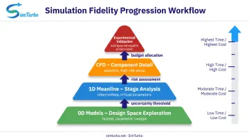
Multi-fidelity strategy:
- Use fast 0D models for design-space exploration and parametric sweeps
- Refine critical parameters with 1D stage analysis
- Apply CFD selectively to components driving uncertainty or risk
- Validate each level against data at the corresponding physical scale
Weigh time, compute budget, required fidelity, available test data, and team skill before you commit. Start with the lowest-fidelity tool that answers the question, then raise resolution only where uncertainty or risk justifies the cost.
Validation and Verification of Simulation Models
Importance of Validation Against Experimental Data
Simulation predictions are only as reliable as the underlying models and assumptions. Validation against test data shows that the model captures the relevant physics, that empirical correlations are appropriate, and that results can support design decisions.
Risks of using unvalidated simulations:
- Incorrect design choices leading to performance shortfalls
- Missed operability limits (surge, stall, overtemperature)
- Safety issues from undetected failure modes
- Wasted resources on hardware that doesn't meet requirements
Validation is not optional for high-stakes engineering decisions.
Verification Versus Validation
Verification asks whether the model is built correctly: equations coded as intended, units consistent, numerics stable, and energy or mass balances closed. Validation asks whether that correct model matches the real engine.
Practical verification checks include unit tests on component blocks, known analytical limits, and steady mass/energy balance residuals. Validation then uses rig or engine data. You need both before trusting a model for design or controls work.
Sources of Validation Data
Common sources, in rough order of accessibility:
- NASA and government centers: Public datasets such as NASA's 2016 J85 modeling study, which publishes component maps and performance data drawn from manufacturer and experimental literature (sources sometimes disagree; document which set you use).
- OEM proprietary tests: Highest fidelity, but rarely available outside the originating company.
- Component rig tests: Compressor maps, turbine efficiency measurements, and combustor pattern factors can validate pieces of the model when full-engine data is missing.
Detailed engine data is often proprietary. Suitable public cases take research, and you should record data provenance with the same care you give the model itself.
Validation Metrics and Acceptance Criteria
NASA's J85 design-point comparison achieved:
| Parameter | Reference | Model | Reported Error |
|---|---|---|---|
| Net thrust | 2,850 lbf | 2,861 lbf | 0.3% |
| TSFC | 0.99 | 0.9901 | 0.01% |
| Shaft speed | 16,540 rpm | 16,540 rpm | 0% |
| Airflow | 44 lbm/s | 44 lbm/s | 0% |
| Compressor PR | 7 | 7 | 0% |
| Turbine-inlet temperature | 2,100 R | 2,097 R | 0.14% |
These are tuned design-point results for a specific case, not universal accuracy targets. Acceptable accuracy depends on application:
- Conceptual design: 5-10% thrust and TSFC accuracy may suffice for trade studies
- Detailed design: 2-5% accuracy on key performance parameters
- Control system certification: Higher precision required, with deterministic timing, limit compliance, and fault-mode coverage
Define acceptance criteria against intended use, test uncertainty, operating envelope, and applicable regulatory authority. Do not turn one study's tuned design-point errors into a universal threshold. Prefer tools that publish comparable checks against public data; SimTurbo, for example, reports J85-GE-21 agreement within ±2% on key performance parameters, which falls in the detailed-design band above.
Applications and Use Cases
Aerospace Design and Development
Simulation supports every phase of engine development:
- Concept selection: Compare cycle options (pressure ratio, turbine temperature, mass flow) for thrust, weight, and efficiency trade-offs
- Preliminary design: Size components, establish performance envelope, predict installation effects
- Detailed design: Optimize blade aerodynamics, cooling effectiveness, combustor emissions, and nozzle expansion
- Integration: Model inlet distortion, bleed air extraction, power offtake, and exhaust system effects
- Certification: Demonstrate compliance with regulatory requirements through analysis and test correlation
Off-design simulation predicts performance across altitude, Mach number, ambient temperature, and throttle setting—the full flight envelope that defines operational capability.
Control System Development and Validation
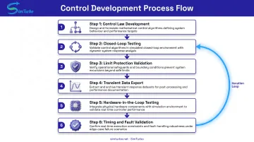
Real-time simulation lets teams prototype and test control algorithms before hardware exists. A typical workflow looks like this:
- Develop control laws in the simulation environment (PID gains, limit logic, fuel scheduling)
- Test closed-loop response during startup, throttle changes, and fault scenarios
- Validate limit protection (overspeed, overtemperature, surge margin)
- Export transient data for external analysis and tuning
- Transition to hardware-in-the-loop (HIL) testing with the physical controller commanding the simulated engine
- Validate deterministic timing, sensor/actuator dynamics, and fault detection logic
Virtual prototyping cuts control-development cost and schedule versus repeated engine-test-cell iteration.
Education and Training
Simulation provides engineering students access to gas turbine principles without expensive hardware. Universities use simulation for:
- Classroom instruction: Interactive demonstrations of Brayton cycle, component matching, and off-design behavior
- Laboratory experiments: Hands-on exploration of compressor maps, surge limits, transient response, and control strategies
- Capstone projects: Student teams design cycles, optimize parameters, and validate performance—building intuition about engine behavior and component interactions
- Graduate research: Advanced cycle studies (intercooling, recuperation, hybrid-electric propulsion) and control algorithm development
Tools like SimTurbo support this with university pricing, classroom and lab programs, and a 30-day free trial. An ASME study reported use of jet-engine simulation in undergraduate propulsion education, confirming the pedagogical value.
Frequently Asked Questions
What is the best engine simulator?
"Best" depends on your goal. CFD tools such as ANSYS Fluent suit detailed component aerodynamics where spatial resolution matters. Component-based platforms like SimTurbo fit system-level performance, real-time transients, and control work. Define the objective first, then choose the fidelity you need at a cost you can sustain.
How accurate are turbojet simulations compared to real engine tests?
Well-validated 0D/1D thermodynamic models typically land within 2–5% on thrust, fuel consumption, and temperatures inside their map calibration range. High-fidelity CFD can match or beat that on detailed flow features when grid, models, and boundary conditions are sound. Off-design accuracy drops with generic maps; always validate against test data for your envelope.
What is the difference between CFD and real-time engine simulation?
CFD solves detailed 3D flow fields at millions of grid points and often takes hours to days on workstations or HPC. Real-time simulation uses lumped thermodynamic models and empirical maps that run in milliseconds on a standard PC. Use CFD for local component design; use real-time models for system dynamics, controls, and training.
Can turbojet simulation software be used for control system development?
Yes. Real-time platforms support algorithm prototyping, closed-loop control-law testing, hardware-in-the-loop checks, and limit-protection evaluation before engine tests. SimTurbo includes built-in PID controllers, limiters, actuators, and sensors, and can export transient data to MATLAB/Simulink.
What are the main challenges in simulating turbojet engines?
The hard parts are full-envelope compressor and turbine maps, combustion and turbulence modeling, component matching, numerical stability in stiff transients, and validation across the flight envelope rather than one design point. Combustion detail must be balanced against compute cost, and control work needs real-time speed without dropping essential dynamics.
How do you validate a turbojet engine simulation model?
Start with test data across altitude, Mach, and throttle. Compare thrust, fuel flow, shaft speed, pressure ratios, and key temperatures; then tune efficiencies, loss coefficients, and map scaling within physical bounds. Document accuracy and weak regions. Code-to-code checks help, but they do not replace experimental validation.
Match fidelity to the job, validate against test data, and know each model’s limits.
Ready to try turbojet simulation? SimTurbo offers a 30-day free trial with component-based engine design, real-time transient simulation, and control development tools. Visit simturbo.net or call (779)-390-4786 to get started.