Compressor thermodynamics provides the analytical foundation for designing, testing, and operating these critical components. By applying the First Law (energy conservation), Second Law (entropy and irreversibility), and appropriate equations of state, engineers can predict power requirements, discharge temperatures, and efficiency metrics for both axial and centrifugal compressors.
This article explores the fundamental thermodynamic principles governing compressors, explains isothermal, isentropic, and polytropic compression processes, defines key performance metrics such as pressure ratio and polytropic efficiency, and examines practical applications including energy recovery, performance testing standards, and real-gas modeling.
Key Takeaways
- Compressor work equals stagnation enthalpy rise; First Law balances energy, Second Law tracks entropy losses
- Polytropic efficiency best measures multistage performance—NASA hit 85.5% at a 4.68:1 pressure ratio (2017)
- Discharge temperature rises with pressure ratio and limits max CPR; intercooling manages heat
- ASME PTC 10 and PTC 22 standardize compressor and gas-turbine performance testing
- Real-gas equations of state are essential at high pressure or near critical points where ideal-gas models fail
Fundamental Thermodynamic Principles for Compressors
First Law of Thermodynamics and Energy Conservation
The First Law of Thermodynamics states that energy is conserved during compression: the mechanical work input equals the increase in gas enthalpy plus any heat lost to surroundings. For a steady-flow adiabatic compressor with negligible kinetic and potential energy changes, the work input per unit mass simplifies to:
w_in = h2 - h1
NASA's stagnation-property form for compressor work is:
CW = ht3 - ht2 = cp(Tt3 - Tt2)
where ht represents total (stagnation) enthalpy, cp is specific heat at constant pressure, and Tt is total temperature. Power consumption becomes:
Ẇ_in = ṁ(h2 - h1)
where ṁ is mass flow rate.
Real-world calculation example: A compressor raising air from 288 K inlet temperature to a 4.68:1 pressure ratio (the benchmark achieved by a 2017 NASA rotorcraft centrifugal compressor) at 85.5% polytropic efficiency needs significantly more shaft work than the ideal reversible case.
The actual enthalpy rise includes friction, turbulence, and tip-clearance losses. Those losses generate entropy and turn extra input energy into unrecoverable heat instead of useful pressure rise.
Second Law of Thermodynamics and Entropy
The Second Law governs irreversibilities: all real compression processes generate entropy (Sgen > 0), reducing efficiency below the reversible ideal. MIT defines lost work as dW_lost/T = dS_gen, directly linking entropy generation to wasted energy.
In an ideal isentropic compression, entropy remains constant (s2 - s1 = 0). Real compressors generate positive entropy from several sources:
- Friction
- Flow separation
- Shock losses
- Heat transfer
That irreversibility shows up as extra temperature rise beyond the ideal case. NASA notes that an 80% efficient compressor exits at a higher temperature than a 100% efficient (ideal) compressor performing the same compression task, because the lost work appears as extra internal energy.
For an ideal gas, entropy change is:
s2 - s1 = cp ln(T2/T1) - R ln(p2/p1)
When entropy increases beyond the isentropic value, it signals irreversibility and efficiency loss.
Enthalpy and Its Role in Compression
Static enthalpy is defined as h = u + pv (internal energy plus flow work). Total (stagnation) enthalpy, neglecting potential energy, is:
ht = h + V²/2
Compressor analysis uses Δht rather than static temperature alone, because stagnation properties account for kinetic energy at the compressor inlet and exit. The First Law establishes that shaft work raises stagnation enthalpy, while the Second Law separately accounts for lost work through entropy generation. The enthalpy increase has two contributors:
- Useful pressure rise (the design objective)
- Irreversible losses (quantified by efficiency)
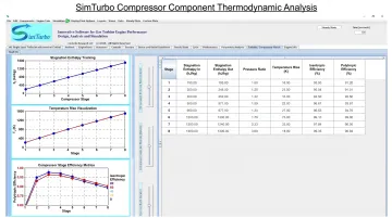
SimTurbo's component-based gas turbine simulation platform models compressors as distinct thermodynamic elements. It tracks stagnation enthalpy changes with pressure ratio, temperature, and efficiency.
The solver applies industry-standard thermodynamic relations and gas-property tables, including real-gas effects and compressor performance maps. Engineers can see how shaft work becomes pressure and temperature change across the Brayton cycle.
Gas Laws and Compressor Behavior
Ideal Gas Law and Compressor Applications
NASA presents the ideal gas equation as pV = nRT, or in specific form pv = RT and p = ρRT, where temperature must be absolute. This model applies well to compressor analysis at moderate pressures and elevated temperatures, where intermolecular forces and molecular volume are negligible compared to thermal energy.
Real gases deviate from ideal behavior, especially at high pressures:
pv = ZRT
Z is the compressibility factor (Z = 1 for an ideal gas). At high discharge pressure ratios, real-gas effects can matter and need station-specific Z values from composition, pressure, and temperature. Examples include the Siemens SGT-800 (about 18.3:1 to 22.0:1) and the GE9X overall pressure ratio near 60:1.
When the ideal-gas assumption holds vs. when it does not:
- Standard air, early stages: Ambient to moderate pressure, roughly 250–400 K; error is usually small
- High-pressure-ratio rear stages: Real-gas equations of state improve accuracy
- Complex gas mixtures: Composition-dependent Z (or a full EOS) is required
Boyle's, Charles's, and Combined Gas Laws
Boyle's Law states pV = constant at constant temperature: volume falls as pressure rises in isothermal compression. Charles's Law states V/T = constant at constant pressure, so temperature and volume scale together. For a fixed mass, the combined gas law joins both effects:
pV/T = constant
NASA shows how this relationship leads to the ideal gas law used above.
In a gas-turbine compressor, compression is fast. Work input raises internal energy faster than heat can leave, so temperature climbs even without external heating. That adiabatic temperature rise is a hard constraint: discharge temperature often caps the pressure ratio you can run.
Material limits track the same constraint. A 1979 NBS/FAA report noted titanium was generally avoided for steady service above about 700 K (800°F) because of creep strength. Modern alloys differ, so use current material specs rather than generic historical ceilings.
Polytropic Relationships
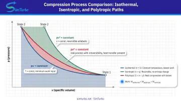
The polytropic relationship generalizes compression paths:
pv^n = constant
The polytropic exponent n sets the process type:
- n = 1: Isothermal (constant temperature)
- n = γ: Isentropic (adiabatic and reversible)
- n between 1 and γ, or above γ: Real compression with heat transfer and irreversibility (typical uncooled stages often run with n > γ)
n ties to efficiency through:
(n - 1)/n = (γ - 1)/(γ·ηₚ)
where ηₚ is polytropic efficiency. This form fits real compressors well because it folds in stage-by-stage irreversibility, so it is the usual basis for multistage performance work and testing.
Types of Compression Processes
Isothermal Compression Process
Isothermal compression holds temperature constant (T = constant) and needs continuous heat rejection so that pV = constant for an ideal gas. It sets the minimum theoretical work between two pressure endpoints:
H_t = RT₀ ln(P₂/P₁)
where R is the specific gas constant, T₀ is the constant temperature, and P₂/P₁ is the pressure ratio.
True isothermal compression needs infinitely slow compression and perfect distributed heat transfer, which a finite gas-turbine compressor cannot deliver. The model still serves as a useful lower-bound benchmark. Practical approximations include:
- Intercooling between compressor stages or sections
- Evaporative/wet compression through inlet water injection
NASA research on 0.71% water/air injection at unchanged throttle reported:
- Thrust up 7.7%
- Specific fuel consumption +0.76%
- Compressor-exit temperature down 43°R (24 K)
- NOx emissions down 14.9%
In tools such as SimTurbo, engineers can place intercoolers in the flow path and compare cooled-compression strategies against this isothermal bound.
Isentropic (Adiabatic) Compression Process
Isentropic compression is both adiabatic (no heat transfer, q = 0) and reversible (no entropy change, Δs = 0). For an ideal gas with constant properties:
pv^γ = constant
and the temperature ratio is:
T₂/T₁ = (p₂/p₁)^((γ-1)/γ)
Most real compressors run closer to isentropic than isothermal because compression is fast and heat transfer is limited. Compressor isentropic efficiency compares ideal isentropic work to actual work:
η_c = (h₂s - h₁)/(h₂ - h₁)
With constant cp, this simplifies to:
η_c = (T₂s - T₁)/(T₂ - T₁)
NASA's compressor work equation divides ideal work by η_c, which is less than 1 for real machines.
Overall isentropic efficiency is a weak multistage metric: it folds in cumulative temperature rise and total pressure ratio instead of a pressure-ratio-independent read of stage aerodynamics. For machines with different pressure ratios or stage counts, polytropic efficiency is the better comparison.
Polytropic Compression Process
Polytropic compression (pv^n = constant) models real compressor performance as a series of infinitesimal stages. Differential polytropic efficiency compares an incremental isentropic enthalpy rise with the actual differential rise:
ηₚ = dh_s / dh
For constant properties:
(n - 1)/n = (γ - 1)/(γ·ηₚ)
Polytropic head is the reversible work integrated along the compression path:
Hₚ = ∫v dp
Exact evaluation for real gases needs an equation of state for v(p, T, composition).
The practical advantage is constant small-stage efficiency that accumulates cleanly across stages. Stage efficiencies add in a logical way, which fixes the multistage problem built into overall isentropic analysis.
ASME PTC 10 uses polytropic methods for head, power, efficiency, surge, and choke when testing single- or multi-casing axial and centrifugal compressors.
A concrete benchmark: the 2017 NASA rotorcraft centrifugal compressor reached 85.5% polytropic efficiency, a 4.68:1 pressure ratio, and 7.5% stall margin at design flow and speed.
Comparison of Compression Processes
| Model | Constraint | Work/temperature result | Appropriate use |
|---|---|---|---|
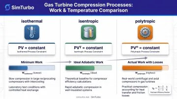
| Isothermal | T = constant | Minimum reversible work (perfect gas) | Lower-bound benchmark; cooled compression |
| Isentropic | q = 0, reversible, Δs = 0 | Ideal adiabatic outlet; η_c reference | Cycle design and compressor-map efficiency |
| Polytropic | Incremental real compression | Stagewise head and efficiency | Multistage comparison, testing, monitoring |
For the same pressure endpoints, isothermal compression needs the least work because temperature—and specific volume—stay fixed. Real adiabatic work exceeds isentropic work whenever η_c < 1, since irreversibilities add enthalpy rise. Use polytropic analysis when you need multistage accumulation and a pressure-ratio-independent efficiency for testing or monitoring.
Compressor Performance Metrics and Calculations
Compressor Pressure Ratio (CPR)
CPR is defined as the ratio of discharge total pressure to suction total pressure:
CPR = pt3 / pt2 ≥ 1.0
CPR is the primary performance indicator. It directly sets:
- Required work input
- Discharge temperature
- Compressor size
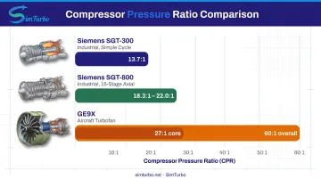
Industrial and aircraft gas turbines cover a wide CPR range by application and architecture:
| Gas-turbine example | Compressor architecture/application | OEM pressure ratio |
|---|---|---|
| Siemens SGT-300 | Industrial, simple cycle | 13.7:1 |
| Siemens SGT-800 | Industrial, 15-stage axial | 18.3:1 to 22.0:1 (configuration-dependent) |
| GE9X | Aircraft turbofan | >60:1 overall, 27:1 core |
At fixed inlet temperature, ideal-gas work and discharge temperature rise with CPR through the exponent (γ - 1)/γ. Higher pressure ratios demand far more work and drive higher exit temperatures, so stage count, materials, and cooling must be sized together.
Polytropic Head and Efficiency
Polytropic head represents the reversible work required for compression:
Hₚ = ∫v dp
evaluated along the actual compression path. Polytropic efficiency accounts for real-world friction, flow losses, and irreversibilities:
ηₚ = (ideal incremental work) / (actual incremental work)
ASME PTC 10 test procedures measure gas quantity, pressure rise, head, shaft power, efficiency, surge, and choke behavior. Results are then corrected to specified gas properties and operating conditions.
Polytropic efficiency is preferred for multistage comparison: it tracks incremental compression quality independent of overall pressure ratio. Overall isentropic efficiency, by contrast, folds in the full compression task.
In SimTurbo, compressor maps relate corrected mass flow to pressure ratio. Performance tables add inlet temperature and pressure, speed, efficiency, altitude, and power so you can compare design-point and off-design operation in one view.
Temperature Rise and Material Constraints
For isentropic compression of an ideal gas:
T₂ / T₁ = (P₂ / P₁)^((γ-1)/γ)
For a polytropic process with constant properties:
T₂ / T₁ = (P₂ / P₁)^((n-1)/n)
NASA states that compressor air heats during compression and exit temperature can become a design constraint because compressor materials have temperature limits. Discharge temperature constraints often govern maximum achievable pressure ratio, particularly in single-shaft or high-CPR configurations.
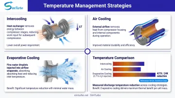
Cooling strategies to manage temperatures include:
- Intercooling between compressor stages or spools
- Air cooling of compressor cases and rotors
- Evaporative cooling via water injection
NASA's wet-compression study showed that 0.71% water/air injection cut compressor-exit temperature by 43°R (24 K). With SimTurbo's component-based intercooler models, you can test staged cooling and quantify effects on Brayton-cycle efficiency and discharge temperature before hardware commits.
Practical Applications and Design Considerations
Energy Recovery from Compression Heat
Compression generates substantial thermal energy. Most of the shaft work input appears as enthalpy rise, and much of it remains in the high-temperature, high-pressure discharge flow. In gas-turbine cycles with recuperation or combined-cycle configurations, that energy can be partially recovered.
An ASME study of intercooled/recuperated cycles reported a 5+ percentage-point efficiency advantage from evaporative compressor aftercooling plus additional water evaporation in the recuperator. Roughly 60% of that gain came from aftercooling and 40% from recuperator evaporation.
SimTurbo models gas-turbine cycles with recuperation, regeneration, and heat recovery, including single-spool turbojets equipped with recuperators. Engineers can add and connect recuperator components to evaluate how compression-related thermal energy might be recovered and reused within the thermodynamic system.
Equations of State and Real Gas Effects
At high pressures, complex compositions, or near critical points, ideal-gas assumptions break down. NIST's 2000 dry-air formulation covers 59.75 to 2000 K and pressures to 2000 MPa using a Helmholtz-energy model that includes ideal-gas, real-gas, and mixing contributions.
When nonideality materially affects density (ρ), enthalpy (h), entropy (s), or the integral ∫v dp, switch to a real-gas equation of state. Do not assign a universal compressibility factor without checking station conditions, composition, and pressure.
SimTurbo's solver accounts for real-gas effects with thermodynamic relations and gas-property tables, so predictions stay reliable across compositions and operating conditions. That matters for non-standard fuels, high-pressure-ratio stages, and multi-component mixtures in design, test, and monitoring work.
Performance Testing and Validation
Thermodynamic principles guide compressor acceptance testing through standards such as ASME PTC 10-2022 (for axial/centrifugal compressors) and ASME PTC 22-2023 (for complete open-cycle gas-turbine plants). These codes specify instrumentation, test procedures, thermodynamic evaluation methods, and reporting formats to ensure consistent, comparable results.
An ASME 2014 fouling case study demonstrated that deposits altered compressor-stage maps and degraded engine performance; modeled washing recovered 30% of lost power. Performance monitoring tracks key indicators to catch degradation early:
- Corrected flow and pressure ratio
- Temperature and enthalpy rise
- Efficiency and power
- Operating-line position
SimTurbo's J85-GE-21 validation against NASA Lewis Research Center test data showed agreement within ±2% for thrust, flow rate, temperature, and thrust-specific fuel consumption (TSFC). The same thermodynamic models used in design can therefore carry through testing and into operational monitoring without a change in basis.
Frequently Asked Questions
What is the working principle of a compressor?
A compressor increases gas pressure by doing mechanical work on the gas, converting shaft power into increased pressure and temperature. NASA explains that shaft work raises airflow total enthalpy, total pressure, and total temperature according to the First Law of Thermodynamics.
What is an air compressor in thermodynamics?
In thermodynamics, an air compressor is a steady-flow device that performs work on air to increase its pressure and energy content (enthalpy). For an adiabatic compressor with negligible kinetic and potential energy changes, work input equals the change in enthalpy: w_in = Δh or Δh_t (using stagnation properties).
What is the difference between a compressor and a condenser?
A compressor consumes shaft work to raise gas pressure and enthalpy through mechanical compression. A condenser rejects heat to convert vapor toward liquid, typically at constant or slightly decreasing pressure, without shaft-work compression. The two devices serve fundamentally different thermodynamic functions in power and refrigeration cycles.
What are the four types of compressors?
The four broad families are:
- Reciprocating (positive displacement using pistons)
- Rotary (positive displacement using screws or vanes)
- Centrifugal (dynamic, radial flow)
- Axial flow (dynamic, axial flow)
Gas turbines principally use centrifugal and axial compressors, with axial designs dominating large industrial and aircraft engines due to higher efficiency and flow capacity.
What is polytropic efficiency in compressors?
Polytropic efficiency is the ratio of ideal reversible (isentropic) work to actual work for an infinitesimal compression stage: ηₚ = dh_s / dh. Because it does not depend on overall pressure ratio and accumulates cleanly across stages, it is the preferred metric for multistage testing and performance monitoring.
How does temperature affect compressor performance?
Per NASA, compressor specific work scales with inlet total temperature at a fixed pressure ratio. Higher inlet temperature lowers density—raising work per unit mass and cutting mass-flow capacity—while discharge temperature limits can cap pressure ratio due to material creep, oxidation, or strength loss.
Compressor thermodynamics ties energy and entropy laws, gas properties, and process models to real performance limits. Platforms such as SimTurbo put those relationships into component-based simulation so teams can check Brayton-cycle behavior and compressor/turbine matching before hardware tests.