This article covers simulation types, essential technical considerations, software selection, best practices, and real-world applications to help you make confident CFD decisions for your turbomachinery projects.
Key Takeaways
- CFD predicts performance, efficiency, and flow behavior before testing, cutting cost and time
- Match the simulation approach (2D/3D, steady/unsteady, multi-stage) to design phase and goals
- Mesh quality, turbulence models, and boundary conditions drive accuracy; set y+ for wall treatment
- Choose software by need: specialized tools for depth, general-purpose platforms for breadth
- Validate models against experimental data to build confidence in predictions
What is Turbomachinery CFD Simulation?
Turbomachinery CFD applies computational fluid dynamics specifically to rotating machinery that transfers energy between a fluid and a rotor. This encompasses compressors, turbines, fans, pumps, and propellers across aerospace engines, power plants, and industrial systems.
CFD must capture several core physical effects:
- Compressible flow effects at transonic and supersonic conditions
- Rotating reference frames and Coriolis/centrifugal forces
- Boundary layer development along blade surfaces
- Secondary flows and endwall vortices
- Shock waves and shock-boundary layer interactions
- Wake interactions between blade rows
CFD solves the Navier-Stokes equations numerically on a discretized domain (mesh), computing velocity, pressure, temperature, and turbulence quantities throughout the flow field. Modern turbomachinery codes typically use finite-volume methods with second-order spatial accuracy and multigrid acceleration for efficiency.
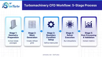
Typical CFD Workflow:
- Geometry preparation – Extract blade passages, tip gaps, and secondary flow paths from CAD
- Mesh generation – Create structured or unstructured grids with boundary layer refinement
- Boundary condition setup – Define inlet/outlet conditions, periodicity, and wall treatments
- Solver execution – Run steady or unsteady simulations with appropriate turbulence models
- Post-processing and validation – Extract performance metrics and compare against experimental data
CFD delivers flow visualization, performance prediction, design optimization, and failure-mode analysis faster and at lower cost than relying on physical testing alone.
NASA's Rotor 37 compressor and film-cooled turbine blade studies show how simulation reveals tip leakage, cooling effectiveness, and loss mechanisms that are difficult or impossible to measure experimentally.
Key Physical Phenomena in Turbomachinery Flows
Complex flow physics make turbomachinery CFD particularly challenging:
- Tip leakage flows – Clearance flow around blade tips creates vortices that reduce efficiency and can trigger stall
- Corner separations – Adverse pressure gradients near blade-endwall junctions cause flow separation
- Laminar-to-turbulent transition – Boundary layer transition affects loss prediction and heat transfer
- Shock-boundary layer interactions – Transonic shocks interacting with viscous wall layers can cause separation
- Unsteady rotor-stator interactions – Periodic wakes and potential fields between blade rows drive time-dependent forcing and acoustic waves
These effects often overlap and couple, so steady RANS alone can miss critical losses—unsteady methods and experimental anchors are usually required for trustworthy results.
Types of Turbomachinery CFD Simulations
Turbomachinery CFD is not one setup. You choose dimensionality, time treatment, viscous modeling, and multi-stage coupling based on design stage and the physics that matter.
Dimensionality: 2D, Quasi-3D, and 3D Approaches
2D simulations suit early design phases, high-aspect-ratio blades, and quick parametric studies where spanwise variations are limited. They cut computational cost but miss secondary flows and tip effects.
Full 3D simulations become the right choice when:
- Complex secondary flows dominate (low aspect ratio blades)
- Tip clearance effects are critical
- Accurate loss prediction is needed
- Blade sweep, lean, or endwall contouring is present
Quasi-3D simulations add source terms to 2D calculations to approximate 3D effects like streamtube convergence and boundary layer blockage. They sit between 2D speed and full-3D fidelity—useful for preliminary work, not final detailed design.
Steady vs Unsteady Simulations
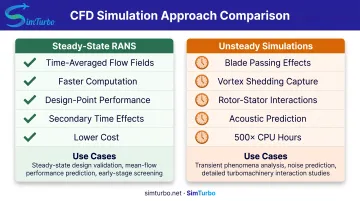
Steady-state RANS (Reynolds-averaged Navier-Stokes) simulations compute time-averaged flow fields. They run faster and suit design-point performance prediction when time-dependent effects are secondary.
Unsteady simulations capture blade passing effects, vortex shedding, rotating stall, and acoustic waves. Use them for:
- Rotor-stator interaction studies
- Flutter and forced response analysis
- Off-design operation and stall prediction
- Acoustic noise prediction
The cost difference is significant: a 2015 axial compressor study found that finest-grid LES required 500 times the CPU hours of URANS, though LES better predicted casing-region time dependence.
Inviscid vs Viscous Modeling
Euler (inviscid) simulations solve for pressure distribution on blades with attached flow. They're appropriate when losses aren't the primary concern and can provide rapid design iterations.
Navier-Stokes (viscous) simulations cover cases that need:
- Loss prediction and efficiency calculation
- Heat transfer analysis
- Separation and stall prediction
- Boundary layer development
While modern computing makes viscous simulations practical for most applications, Euler methods remain valuable for quick parametric sweeps early in design.
Multi-Stage Simulation Methods
Mixing plane approach:
- Circumferentially averages flow at blade row interfaces
- Steady-state calculation
- Industry standard for multi-stage performance prediction
- Removes unsteady blade-passing effects
Frozen rotor method:
- Holds rotor-stator relative position fixed
- Steady-state with preserved circumferential nonuniformity
- Useful as initial condition for unsteady simulations
- Captures one clocking position only
Sliding mesh / time-accurate methods:
- Captures full blade passing effects and rotor-stator interactions
- Required for unsteady forcing, acoustics, and blade-row timing studies
- Computationally expensive; used when true unsteady blade-row interaction must be resolved (Ansys CFX documentation)
Rolls-Royce uses unsteady CFD to calculate blade-row forcing and assess self-induced vibration risk. That is a direct durability use case for time-accurate methods.
Essential Components of Turbomachinery CFD
Accurate turbomachinery CFD depends on four foundations: mesh quality, boundary conditions, turbulence model choice, and convergence discipline. Weakness in any one of them undermines even a capable solver.
Mesh Generation and Quality Requirements
Resolution guidelines:
- 100,000-400,000 cells for wall-function meshes (design iterations)
- 400,000-1,000,000+ cells for wall-resolved boundary layers (high-fidelity performance)
- 100+ cells along blade surfaces
- 10-20 cells around leading/trailing edges
NASA's film-cooled turbine blade calculation used 1,987,520 cells including 172 cooling holes with 80 cells at each hole exit, demonstrating the resolution needed for complex cooling geometries.
Boundary layer meshing:
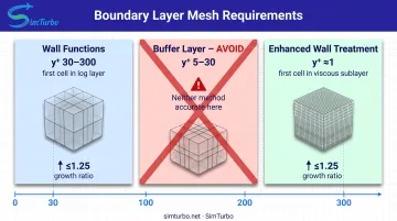
- Wall functions: y+ 30-300, first cell in log layer
- Enhanced wall treatment: y+ ≈ 1 (up to 5), first cell in viscous sublayer
- Growth ratio: ≤1.25 normal to walls (NASA used 0.8-1.25 ratios)
Ansys explicitly warns against first-cell placement in the y+ 5-30 buffer layer, where neither wall functions nor low-Reynolds-number models are accurate.
Mesh topology: Structured hexahedral meshes offer better accuracy and efficiency for blade passages, while unstructured meshes handle complex geometries like tip gaps and secondary air systems.
Boundary Conditions and Setup
Inlet conditions:
- Total pressure and total temperature (typical for compressors/turbines)
- Flow angles or velocity components
- Place inlet boundary 1-2 blade chords upstream when possible
Outlet conditions:
- Static pressure (most common)
- Mass flow rate (useful for matching test conditions)
- Place outlet boundary 2-3 blade chords downstream to avoid backflow
Turbulence inlet specifications:
- Intensity: 1-20% depending on upstream components (higher for combustor exit, lower for clean inlet)
- Length scale or eddy viscosity ratio: 10-10,000 depending on application
Periodic boundaries: Required for single-passage runs so one blade passage represents the full annulus at far lower cost.
Turbulence Modeling Selection
Common turbulence models:
| Model | Strengths | Weaknesses |
|---|---|---|
| Spalart-Allmaras | Robust, good for attached flows, efficient | Less accurate for separated flows |
| k-epsilon | Widely used, stable | Over-production in stagnation regions |
| k-omega SST | Better near-wall behavior, popular for aerospace | More sensitive to freestream values than original k-omega |
| v2-f | Improved stagnation region handling | More complex, higher computational cost |
Menter's SST formulation was designed to remove arbitrary freestream sensitivity and account for principal-shear-stress transport in adverse-pressure-gradient boundary layers—critical for turbomachinery with strong pressure gradients.
Selection criteria:
- Simple algebraic models: Attached design-point flows with mild pressure gradients
- Two-equation models: Separated flows, secondary flow prediction, general turbomachinery
- Transition models: Cases where laminar-to-turbulent transition significantly affects losses or heat transfer

Convergence and Validation
Convergence criteria:
- Residual reduction targets (typically 3-6 orders of magnitude)
- Monitoring integrated quantities: mass flow, pressure ratio, torque, efficiency
- Thermal field convergence for heat transfer cases (may lag momentum field)
Mesh independence: NASA recommends refinement ratio r ≥ 1.1 between levels and three grids for estimating observed order and checking the asymptotic range. Calculate Grid Convergence Index (GCI) to quantify discretization uncertainty.
Validation: Compare simulation results against experimental data or benchmark cases. ASME V&V 20 standard requires including both numerical and experimental uncertainties when assessing simulation accuracy.
NASA's challenge for full-engine simulation envisions about 10^9 cells for a main-path sector and 10^11-10^12 cells with secondary flow paths, but these are future research targets, not typical production meshes.
Choosing the Right CFD Software for Turbomachinery
The CFD software landscape includes general-purpose commercial codes, specialized turbomachinery platforms, and open-source alternatives. Each category offers distinct advantages depending on your application, budget, and expertise.
General-purpose commercial codes:
- Ansys CFX: Built for turbomachinery with rotor-stator models, multistage CFD, transient blade row, and harmonic balance methods
- Ansys Fluent: General CFD with MRF, sliding mesh, and mixing-plane interfaces, plus multiple averaging options
- Simcenter STAR-CCM+: Integrated motion models, mixed mesh types, adaptive refinement, and scalable CPU/GPU solvers
Specialized turbomachinery platforms:
- Cadence Omnis / Fine Turbo: End-to-end CAE with a structured density-based solver, AutoGrid mesher, and nonlinear harmonic method
- Ansys TurboGrid: Blade-passage mesh generator (not a solver) for axial, radial, and mixed-flow configurations, including tip clearance
Design and integration environments:
- Concepts NREC AxCent: 3D design suite with TurboLink that launches Fine Turbo, imports CFD results, and connects to multiple solvers
Open-source alternatives:
- OpenFOAM: General CFD suite; pimpleFoam handles transient rotating fans with arbitrary mesh interface coupling
- SU2: A 2024 ASME study validated NASA Stage 35 steady results against measurements, with full-annulus inlet-distortion behavior comparable to CFX
Key features to evaluate:
- Turbomachinery-specific capabilities (mixing planes, rotating zones, periodic boundaries)
- Turbulence model selection and near-wall treatment options
- Meshing tools or compatibility with external mesh generators
- Parallel scalability and HPC support
- User interface ease and learning curve
- Validation database and documentation
- Cost structure: perpetual license versus subscription, academic pricing
CFD answers detailed flow-field questions inside blade rows and passages. Gas turbine programs still need a separate system-level view of how those components behave together across the full engine cycle.
That is where tools such as SimTurbo fit. It is a Windows-based, component-level gas turbine simulator—not a CFD solver—with drag-and-drop architecture, real-time steady and transient modeling, and reported validation within ±2% of NASA J85-GE-21 test data. Engineers can assemble inlets, compressors, combustors, turbines, nozzles, shafts, and controls, then use the results alongside CFD when matching components or checking off-design behavior.
Rolls-Royce adopted its HYDRA CFD code company-wide in 2009 for Trent 1000 and Trent XWB design, using it for efficiency prediction, blade-row forcing, and vibration risk assessment—demonstrating how specialized tools can become integral to a company's design process.
Match the tool to the question you need answered. Use general-purpose codes when you need broad multiphysics coverage; pick specialized turbomachinery solvers when multistage or harmonic methods dominate the workflow; and keep a system-level engine model in the loop when component CFD must still close on cycle performance, operability, and controls.
Best Practices for Accurate Turbomachinery CFD Simulations
Accurate turbomachinery CFD depends as much on disciplined process as on solver choice. The practices below catch the errors that most often invalidate results—then keep runs efficient once the setup is sound.
Common Pitfalls to Avoid
- Insufficient mesh resolution near walls (leading to y+ mismatch with turbulence model)
- Incorrect y+ values for chosen wall treatment (especially the 5-30 buffer layer)
- Unrealistic turbulence inlet conditions (too high or too low intensity)
- Premature convergence declaration based on residuals alone
- Over-reliance on default solver settings without understanding their implications
Once those traps are off the table, lock in a repeatable QA loop before you trust any performance number.
Quality Assurance Workflow
- Geometry verification – Check blade angles, tip gaps, fillet radii match design intent
- Mesh quality checks – Inspect aspect ratio, skewness, growth rates; target <0.85 skewness
- Boundary condition validation – Ensure inlet/outlet placement, turbulence values, and periodic boundaries are correct
- Monitor convergence history – Track mass flow, pressure ratio, torque, and efficiency, not just residuals
- Compare against physics expectations – Do pressure distributions, Mach numbers, and blade loading make sense?
- Validate against prior data – Benchmark against experimental results or higher-fidelity simulations when available
- Document assumptions and uncertainties – Record mesh resolution, turbulence model, and known limitations
With accuracy checks in place, these habits cut wall-clock time without weakening the result.
Efficiency Tips
- Start with coarse mesh and steady simulation before refining
- Use solution from similar case as initialization
- Use adaptive time-stepping for unsteady runs (reduces wall-clock time)
- Use HPC resources for production simulations (modern codes scale to hundreds of cores)
- Generate consistent coarse meshes by removing alternate grid lines for convergence studies
Residual reduction alone does not prove accuracy. Mesh independence and validation against data or higher-fidelity runs remain essential.
Applications and Use Cases of Turbomachinery CFD
Aerospace applications
Jet engine compressor and turbine design relies on CFD for performance prediction across the operating envelope. Engineers use simulation to:
- Optimize blade shapes for efficiency and stall margin
- Predict performance at varying altitudes and Mach numbers
- Design cooling systems for hot-section components
- Couple CFD with structural analysis for blade durability
NASA's film-cooled turbine blade work with 172 cooling holes shows how CFD resolves complex internal and external flows while balancing cooling effectiveness against aerodynamic efficiency.
Power generation and industrial uses
The same methods transfer beyond flight hardware. Gas turbine power plants use CFD to raise efficiency and cut emissions. Steam turbines, automotive turbochargers, and industrial pumps also depend on detailed flow analysis for design trades.
Rolls-Royce extended its HYDRA CFD platform across gas turbines, air/thermal systems, and power generation, so teams apply consistent analysis methods from aerospace to industrial plants.
Educational and research applications
Universities use turbomachinery CFD and related engine simulation to teach gas turbine principles with hands-on models. SimTurbo complements that path: students visualize steady-state and transient engine behavior in real time, support capstone work on UAV or hybrid-electric propulsion, and explore novel configurations without a full test cell.
Real-time runs make startup sequences, throttle response, and compressor surge easier to study than in a physical lab alone. MIT's Gas Turbine Laboratory and similar programs pair simulation with experimental facilities so graduates leave fluent in both analysis and test.
Frequently Asked Questions
What is turbomachinery used for?
Turbomachinery covers rotating machines—compressors, turbines, fans, and pumps—that transfer energy between fluids and rotors. They power aircraft engines, generate electricity, drive turbochargers, and move fluids in aerospace, energy, and manufacturing.
Which CFD software is best?
It depends on your application, budget, and team skills. Commercial codes such as CFX, Fluent, and STAR-CCM+ cover broad physics; FINE/Turbo goes deeper on turbomachinery; OpenFOAM and SU2 add flexibility without license fees but need more user expertise.
What is turbomachinery CFD simulation?
It uses computational fluid dynamics to predict gas or liquid flow through rotating machines such as compressors, turbines, fans, and pumps. Solving the Navier-Stokes equations yields velocity, pressure, temperature, and turbulence fields so you can estimate performance before physical testing.
What are the main challenges in turbomachinery CFD?
Main issues include rotating reference frames, scales from thin boundary layers to full passages, turbulence models that struggle with transition and separation, and the cost of unsteady multi-stage work (LES can need ~500× RANS resources). Engine-scale validation data is scarce, and the y+ 5–30 buffer layer is hard to model well.
How long does a turbomachinery CFD simulation take?
Geometry and meshing often take days to weeks. Steady single-stage runs can finish in hours on a workstation; unsteady multi-stage or LES cases may need days to weeks on HPC. Full projects from setup to validated results usually span weeks to months.
What mesh resolution is needed for turbomachinery simulations?
Design studies often use 100,000–400,000 cell wall-function meshes (y+ 30–300). High-fidelity work typically needs 400,000–1,000,000+ cells with wall-resolved layers (y+ ≈ 1). Always run mesh-independence studies with a refinement ratio ≥1.1 instead of trusting generic cell counts.