Key Takeaways
- Turbine design software is an integrated tool chain from 0D cycle models through 3D CFD and structural analysis—not a single solver
- Shortlist by application first: gas, steam, wind, and hydro need different physics models and validation standards
- Component-based GUI tools speed architecture trades and off-design studies; CFD-coupled tools resolve 3D flow at higher cost
- Off-design performance, transient operation, and control validation add the most value beyond steady-state design points
- Weigh turbine type, fidelity needs, map provenance, team expertise, and domain validation standards when you choose
What Is Turbine Design Software?
Turbine design software comprises specialized engineering platforms that enable virtual design, simulation, analysis, and optimization of turbomachinery systems. These tools model fluid flow, thermodynamics, mechanical stresses, and energy conversion in rotating machinery. They replace or augment methods that once depended on empirical formulas, manual calculations, and extensive physical testing.
The field has evolved significantly over five decades. NASA documented a preliminary axial-flow turbine design program in 1972, daily industrial use of NASA turbomachinery routines by 1978, and the Numerical Propulsion System Simulation (NPSS) beginning in 1995.
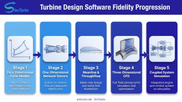
Today's platforms integrate multiple analysis levels:
- Zero-dimensional cycle models
- One-dimensional network solvers
- Meanline and throughflow blade design
- Three-dimensional CFD and finite element analysis
- Coupled system simulation
NPSS spans 0D component models through 3D detailed codes. That range defines modern turbine software as a multifidelity tool chain, not a single black-box solver.
Component-based architectures let engineers assemble systems from compressors, combustors, turbines, nozzles, shafts, sensors, actuators, and controllers, then connect and re-parameterize them graphically. The model stays transparent, so teams can run rapid architecture trades against the underlying physics.
Integrated system models embed component behavior in validated maps or correlations and solve the coupled thermodynamic and mechanical system at once. They trade some transparency for speed and reliable convergence in off-design or transient work.
Key Capabilities of Turbine Design Software
Modern turbine design platforms provide five core capabilities, each addressing a critical aspect of turbomachinery performance:
Aerodynamic and Thermodynamic Simulation
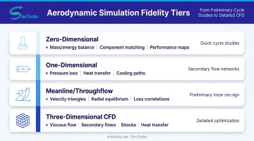
Platforms model fluid flow, pressure ratios, temperature distributions, and energy-conversion efficiency across turbine stages. Fidelity typically scales as follows:
- Zero-dimensional cycle tools — mass and energy balances with component matching and performance maps
- One-dimensional network models — pressure loss, heat transfer, and secondary-air or cooling-flow paths
- Meanline and throughflow solvers — velocity triangles, radial equilibrium, and loss correlations for preliminary blade paths
- Three-dimensional CFD — viscous flow, secondary flows, wakes, shocks, and local heat transfer simpler models miss
Geometry and Blade Design
Engineers create and optimize blade profiles, airfoil shapes, twist angles, and stacking lines for higher stage efficiency. Parametric meridional paths, stacking tools, and inverse or direct design methods open design spaces that manual calculation cannot cover quickly.
Many platforms export geometry straight to CFD or manufacturing CAD, linking conceptual design to detailed analysis.
Structural and Mechanical Analysis
Turbine blades and rotors see extreme centrifugal loads, thermal gradients, and vibratory excitation. Structural modules evaluate stress, modal and forced response, Campbell diagrams, and critical speeds.
Coupled thermal-structural analysis accounts for temperature-dependent material properties and thermal expansion. Rotordynamics tools model lateral, torsional, and axial rotor-bearing behavior so teams can predict stability margins and stay clear of resonance.
Performance Mapping
Characteristic curves show how a turbine behaves in steady-state and transient operation, off-design points, and changing inlet conditions. Software builds maps of corrected speed, flow, pressure ratio, efficiency, and limits such as surge, choke, or cavitation.
Those maps feed cycle analysis, control design, and operability studies that confirm the design meets mission requirements across the full envelope.
Control System Integration and Validation
Many platforms ship control-component libraries so teams can validate algorithms before hardware is built:
- PID controllers, limiters, and governors
- Actuators and sensors
- Startup, load-change, shutdown, and fault scenarios in real-time or accelerated transient runs
Exporting plant responses to tools such as MATLAB/Simulink or Python supports controller tuning and hardware-in-the-loop migration. Specialized gas-turbine environments (including platforms like SimTurbo) often pair these libraries with cycle and transient engine models so control design stays tied to plant physics.
Types of Turbine Design Software by Application
Turbine design software is not one-size-fits-all. Gas, steam, wind, and hydro turbines operate on fundamentally different thermodynamic cycles, fluid media, and structural constraints, requiring specialized tools.
Gas Turbine Engine Software
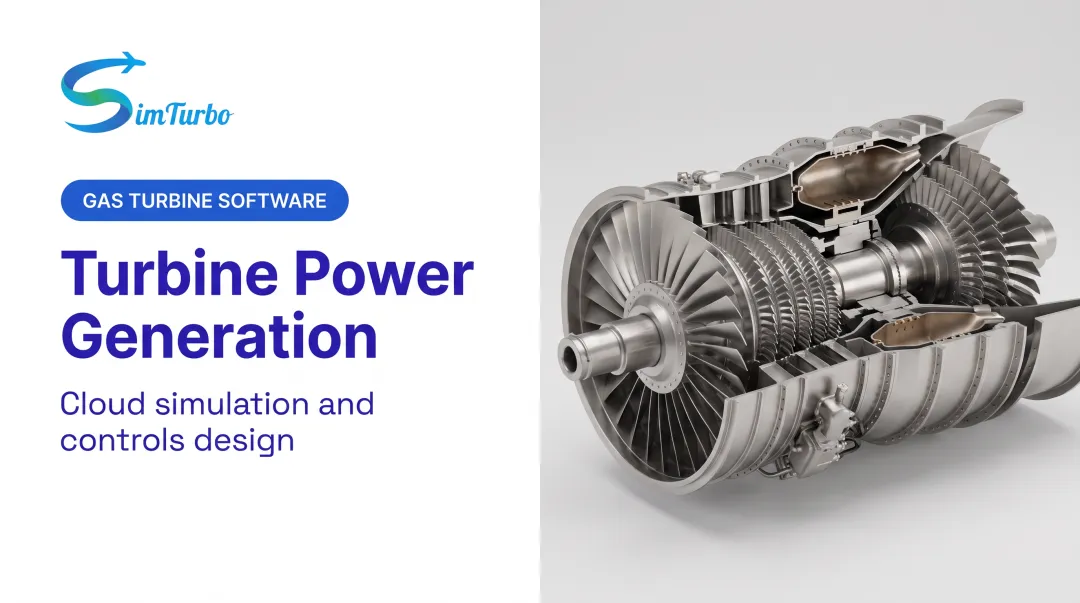
Gas turbine platforms focus on Brayton-cycle thermodynamics, compressor-turbine matching, combustion, and high-temperature aerodynamics. Component-based systems model inlets, compressors, combustors, turbines, nozzles, afterburners, recuperators, and shaft dynamics.
GasTurb calculates and optimizes performance for propulsion and power-generation setups, including off-design operation, transient heat soak, tip-clearance effects, and control studies. NPSS, an object-oriented nonlinear thermodynamic environment first developed by NASA Glenn engineers, supports preliminary design, off-design, transient, and flight-test correlation modes with external-tool integration.
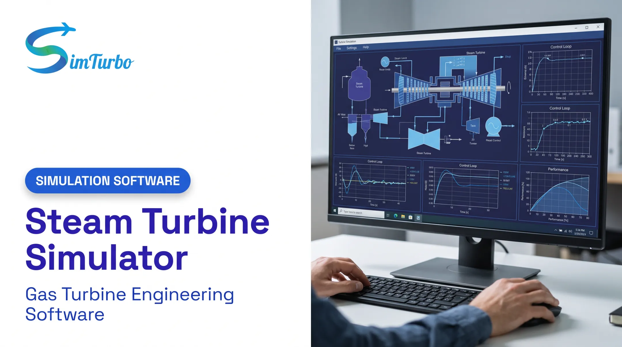
SimTurbo is a Windows-based gas turbine simulation platform with drag-and-drop components. Engineers arrange inlets, compressors, combustors, turbines, nozzles, shafts, sensors, actuators, and control blocks, then run single-spool and dual-spool turbojets, recuperated engines, and aero-derivative power systems in real time on standard PCs.
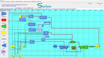
Its J85-GE-21 single-spool turbojet model was validated against NASA Lewis Research Center test data, within ±2% on thrust, airflow, temperature, and thrust-specific fuel consumption. Typical uses and access options include:
- Aerospace, power-generation, and classroom or lab workflows
- 30-day free trial and flexible seat licensing (e.g., $59.99/month, $599/year, or $5,999 lifetime)
Flownex models one-dimensional thermal-fluid networks for secondary air, blade cooling, combustion, and lubrication, and couples with Ansys Mechanical and CFX for localized 3D studies. AxSTREAM ties 0D/1D systems, turbomachinery design, performance maps, off-design and transient analysis, CFD, FEA, cooling, and rotordynamics into one workflow.
Steam Turbine Design Software
Steam turbine tools optimize Rankine-cycle performance, multi-stage layout, moisture-fraction management, and reheat or regenerative setups. Most platforms also fold in heat-balance analysis for power-plant and combined-cycle work.
Common options include:
- AxSTREAM System Simulation — Rankine-cycle and thermal-fluid modeling tied to multistage turbine and rotordynamic workflows
- Concepts NREC Agile/AXIAL — Multistage axial meanline design for gas, steam, and hydraulic turbines, with steam and ORC material for reheat and wetness separation
Wind Turbine Design Software
Wind turbine platforms couple aerodynamics, structural dynamics, and controls, plus hydrodynamics for offshore machines.
Widely used tools include:
- OpenFAST — NREL’s open-source whole-turbine and wind-farm code for coupled aeroelastic, hydrodynamic, and control analysis, with nonlinear time-domain load cases aligned to IEC 61400
- DNV Bladed — Onshore and offshore loads, stability, controller design, and certification
- QBlade — Horizontal- and vertical-axis aero-servo-hydro-elastic simulation with integrated solvers and dynamic-wake modeling
Hydro Turbine Design Software
Hydro tools address head, flow, specific speed, free-surface or multiphase cavitation, and draft-tube dynamics for Francis, Kaplan, Pelton, and related machines.
- TURBOdesign Suite — 3D inverse blade design and optimization aimed at efficiency and cavitation
- CFturbo — Conceptual axial, radial, and mixed-flow turbine design with CFD/FEA and optimization interfaces
A peer-reviewed ASME study of a Francis turbine rehabilitation with CFD-based design reported over 3% higher peak efficiency and a 13% power upgrade versus the original runner. Gains like these are project-specific, but they show what simulation-driven optimization can deliver.
How to Select Turbine Design Software
Choosing the right platform requires aligning software capabilities with project requirements, validation standards, and team expertise.
Assess Turbine Type and Application Requirements
Match software specialization to your engineering domain:
- Gas turbines: Compressible flow, high-temperature combustion, and transient operability
- Steam: Rankine-cycle integration, moisture modeling, and multi-stage extraction
- Wind: Coupled aeroelastic loads and IEC design-load-case support
- Hydro: Cavitation, draft-tube pressure fluctuations, and model-test scaling
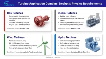
Using a gas-turbine cycle tool for wind structural loads, or a wind code for steam reheat, will fail.
Evaluate Validation and Accuracy Standards
Confirm the software is validated against experimental data, published benchmarks, or industry standards. Common acceptance references include:
- ASME V&V 20: CFD and heat-transfer verification and validation
- ASME PTC 22-2023: Gas-turbine corrected power and heat rate
- ASME PTC 6: Steam-turbine acceptance
- IEC 60193:2019: Hydraulic-turbine model acceptance
- IEC 61400 load cases: Wind certification
Prefer platforms that publish grid-independence studies, turbulence-model benchmarks, and test-data comparisons with quantified uncertainty over those that only claim qualitative "industry validation."
Consider Team Expertise and Learning Curve
Decide whether your team needs deep CFD skill or a component-based graphical workflow:
- Drag-and-drop GUIs and component libraries: Faster setup and cycle studies for turbomachinery engineers without heavy computational backgrounds; may hide correlations and limit customization
- Open, object-oriented models: Better traceability and room to change physics or add proprietary correlations; need scripting skill and domain expertise
- Full 3D CFD: Requires meshing, turbulence and multiphase choices, convergence monitoring, and formal V&V—skills not every design team has
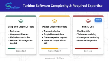
Pick the tier that matches the work you run most often, not the most powerful option on paper.
Benefits of Using Turbine Design Software
Turbine design software delivers three primary benefits that justify its adoption across aerospace, power, and renewable-energy sectors.
Reduced development time and cost through rapid virtual prototyping, parametric studies, and design iteration without physical hardware. A major engine manufacturer estimated that integrated simulations could reduce design and development time and cost by approximately 30%-40% through fewer redesigns. That figure is one company's estimate, not a measured industry average.
Virtual testing opens design spaces that would be prohibitively expensive to prototype physically:
- Blade counts and stagger angles
- Cooling schemes
- Control strategies
Improved turbine performance and efficiency through optimization algorithms that explore design spaces beyond manual calculation. Modern solvers can evaluate thousands of geometry or operating-parameter combinations, identifying configurations that maximize efficiency, minimize weight, or extend operability margins.
The CFD-based Francis-turbine rehabilitation case achieved over 3% higher peak efficiency and a 13% power upgrade, showing measurable performance gains from simulation-driven design.
Enhanced understanding of transient behavior, off-design operation, and failure modes that are difficult or expensive to test physically. Transient simulations reveal startup dynamics, load-rejection response, compressor surge onset, and control-system interaction.
Off-design maps show how efficiency degrades at part load or how a wind turbine responds to turbulent inflow. Failure-mode studies simulate sensor faults, actuator failures, or extreme environmental conditions safely in software, informing design robustness before hardware testing.
Frequently Asked Questions
What is turbine design software used for?
Turbine design software lets engineers virtually design, simulate, analyze, and optimize turbomachinery before physical prototyping. It cuts development cost and cycle time by testing design alternatives, control algorithms, and off-design behavior in a risk-free environment.
What is the most efficient turbine design?
Efficiency depends on the application. Reaction turbines (e.g., Francis, multi-stage steam) suit high-flow, moderate-head duty; impulse machines like Pelton wheels fit low-flow, high-head sites. Design software tunes each type to its operating conditions and fluid properties.
What are the four types of turbines?
The four main turbine types are steam turbines (power generation via Rankine cycle), gas turbines (aerospace propulsion and power generation via Brayton cycle), wind turbines (renewable energy from atmospheric flow), and hydro turbines (hydroelectric power from water flow). Each type operates on different thermodynamic principles and requires specialized design tools.
How accurate is turbine simulation software?
Accuracy depends on model fidelity, validation data, turbulence modeling, and grid resolution. SimTurbo’s validated J85-GE-21 gas turbine simulation achieved ±2% accuracy against NASA test data for thrust, flow, temperature, and fuel consumption. Results should still be quantified for the specific quantity and operating point.
Can turbine design software simulate control systems?
Yes. Advanced platforms include control libraries such as PID controllers, limiters, governors, actuators, and sensors. Engineers can build closed-loop controls, test startup and shutdown, validate fuel scheduling and surge protection, and export responses for hardware-in-the-loop work.
Do I need CFD expertise to use turbine design software?
It depends on the platform. Component-based tools with graphical interfaces (cycle simulators, meanline codes) are usable without specialized CFD training. Full 3D CFD-coupled work still needs meshing, turbulence-model selection, convergence checks, and formal V&V skills.