That's not a hypothetical. It's the baseline engineering reality behind every jet engine, marine gas turbine, and power-generation unit built in the last five decades. Cooling isn't a bonus feature added for durability — it's what makes high-temperature, high-efficiency operation possible at all.
This article breaks down how turbine blade cooling actually works, the main methods engineers use, and how those methods get chosen for a specific application.
TL;DR
- Turbine blades are cooled primarily with compressor bleed air routed through internal passages and surface holes
- Four primary approaches: internal convection/impingement cooling, film cooling, transpiration cooling, and thermal barrier coatings
- Method selection depends on turbine stage, temperature exposure, and manufacturing complexity
- Cooling design decisions directly affect engine efficiency, blade life, and maintenance costs
What Is Turbine Blade Cooling?
Turbine blade cooling is the set of engineering techniques used to keep blade metal temperature below its melting threshold while the surrounding combustion gas runs hotter than that threshold.
Here's how it typically works:
- Air is bled from later compressor stages, where it's already been pressurized
- That air routes through internal ducts machined or cast into the blade
- It exits through precision-drilled holes or porous surfaces to protect the exterior
Cooling is a core structural requirement of modern turbine design. An uncooled blade at today's turbine inlet temperatures would fail within seconds.
Why Is Turbine Blade Cooling Important?
The Efficiency-Temperature Relationship
Higher turbine inlet temperature generally supports higher thermal efficiency, which is why engineers keep pushing operating temperatures upward. But the relationship isn't as simple as "hotter equals better."
A NASA cycle study found that reducing vane coolant by roughly 5.5% of compressor-discharge airflow increased cycle efficiency by about 0.4%, with broader first-stage coolant reductions improving it by nearly 1%. Cooling air itself carries an efficiency cost. Every pound of air diverted for cooling is air not doing useful work in the combustion cycle.
An earlier NASA model examining turbine inlet temperatures from 1,278 to 1,944 K found that efficiency response to higher TIT could be positive, flat, or even negative, depending on coolant temperature ratio and pressure coefficient. There's no universal rule that says "more heat always means more efficiency." It depends on how well the cooling system is designed around that specific temperature target.
What Happens Without Adequate Cooling
Inadequate cooling shows up as:
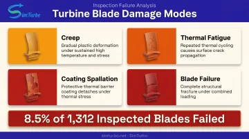
- Creep — slow, permanent deformation under sustained heat and stress
- Thermal fatigue — cracking from repeated heating and cooling cycles
- Coating spallation — protective layers flaking off, exposing bare metal
- Outright blade failure — the outcome when the damage modes above go unchecked
A NASA field study inspecting 1,312 first-stage high-pressure turbine blades found 111 blades, or 8.5%, cataloged as failed. Among those failures, roughly 20% involved thermal-mechanical fatigue and 21% involved oxidation or erosion — both directly tied to thermal exposure.
Hot Streaks Complicate the Picture
Combustor exit temperatures aren't uniform. Localized "hot streaks" hit certain blade regions harder than others, which means cooling can't be designed as a blanket solution. Engineers need to know exactly where the thermal load concentrates and design cooling geometry around it.
That's where simulation tools earn their place. Modeling these thermal-fluid interactions before committing to hardware saves time and cost in cooling design.
Types of Turbine Blade Cooling Methods
No single method covers every blade region or application. Designers combine approaches based on thermal load, blade location, and cost constraints. Broadly, methods fall into two categories:
- Passive protection — thermal barrier coatings
- Active air-cooling — internal and external methods that consume compressor bleed air
Internal (Convection & Impingement) Cooling
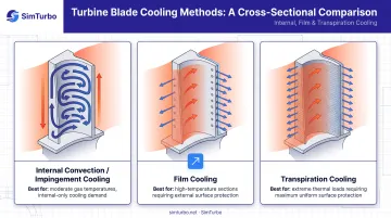
Cooling air flows through serpentine internal passages lined with trip strips, pulling heat away through convection. Impingement cooling takes this further by directing air jets straight at hot internal surfaces for concentrated heat transfer.
What makes it different: heat leaves the blade through internal airflow, without any coolant reaching the external surface. Film and transpiration cooling, by contrast, put coolant on or through the outer surface.
Best suited for:
- Rotor blades
- Regions where disrupting the external airflow isn't acceptable
Strengths: removes heat effectively without altering the blade's outer aerodynamics.
Limitations:
- Less effective alone at the highest gas temperatures
- Often paired with another method for extreme heat; one NASA test found venting spent impingement air through film holes raised local heat transfer by 20–30% in a specific configuration
Film Cooling
Film cooling ejects air through small surface holes to create a thin protective layer between the hot gas path and the blade metal.
What makes it different: it protects the surface directly, rather than only cooling from inside.
Best suited for:
- Leading edges
- High-pressure turbine blades
- Areas exposed to combustor hot streaks
The key evaluation metric here is cooling effectiveness, defined as:
$$\eta = \frac{T_\infty - T_{aw}}{T_\infty - T_c}$$
Where a value of 0 means no benefit and 1 means the wall reaches coolant temperature. This gives engineers a standardized way to compare film-cooling configurations.
Strengths: widely used; balances cooling performance against manufacturing cost and aerodynamic penalty better than most alternatives.
Limitations:
- Increases aerodynamic drag and causes pressure loss
- Adds manufacturing complexity from precision-drilled holes
- One AIAA study on an optimized blade found mean efficiency dropped by just 0.06%, a small but real penalty that varies by geometry and blowing ratio
Transpiration & Full-Coverage Film Cooling
Instead of discrete holes, coolant passes through a porous wall or dense hole array, creating a far more continuous protective layer than standard film cooling.
What makes it different: it distributes coolant more uniformly, closing the gaps between individual film-cooling holes.
Best suited for: extreme thermal environments where standard film cooling can't keep up.
Strengths: one 2021 turbine-blade panel experiment reported film effectiveness above 95%. Another study found transpiration cooling efficiency 34% higher than effusion cooling and 25% higher than internal cooling on a vane-wall test.
Limitations:
- NASA engine tests with porous woven-wire blade shells showed large random permeability variation and uneven cooling
- Some blade tips failed within 10 minutes; an improved-tip design lasted 33 hours, still far short of production life
Transpiration cooling's performance ceiling is high, and so is its manufacturing risk. That gap is why it still sees limited adoption after decades of research.
Thermal Barrier Coatings (Passive Protection)
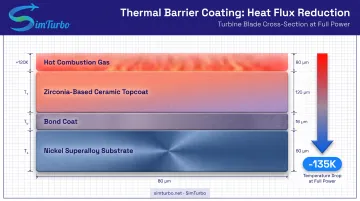
A ceramic topcoat, typically zirconia-based, applied over a bond coat to reduce heat flux into the blade metal.
What makes it different: it works passively. No compressor air is consumed, unlike every active cooling method above.
Best suited for: supplementing air cooling on high-pressure turbine blades, especially at leading edges.
Strengths: one NASA turbine test measured a temperature drop of up to 135 K through the coating at full power, easing the load on the active cooling underneath.
Limitations:
- Coatings degrade with cyclic thermal exposure
- NASA life-prediction models were generally accurate within a factor of 3 of observed test life, a wide margin that shows how condition-dependent coating life is
- Coating loss exposes bare substrate to accelerated damage, which is why TBCs are never used as a standalone solution
How to Choose the Right Cooling Method
There's no "most advanced" method that wins by default. The right combination depends on where the blade sits, what mission profile the engine flies, and what the budget allows.
Key factors to weigh:
- Gas path temperature and stage position — high-pressure turbine blades face far more thermal stress than later-stage blades
- Cooling effectiveness vs. aerodynamic penalty — every cooling method that touches the external surface costs some efficiency
- Manufacturing complexity and cost — hole drilling, coating application, and porous structures all carry different price tags
- Duty cycle — continuous power generation loads differ dramatically from frequent start-stop aerospace missions
- Simulation and validation capability — modeling thermal-fluid behavior before committing to hardware avoids expensive rework
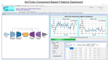
That last point matters more than it might seem. Platforms like SimTurbo let engineers build component-based engine models (inlets, compressors, combustors, turbines, nozzles) and simulate steady-state and transient behavior in real time. Users can export results to CSV or Excel and continue analysis in MATLAB or Python.
SimTurbo's validated dataset (accurate within ±2% against NASA J85-GE-21 test data) covers system-level performance metrics like thrust and TSFC, not blade-cooling-passage detail. For cycle trade-off studies, that real-time engine-level modeling still gives engineers a faster way to test assumptions before hardware testing begins.
Common Mistakes to Avoid When Designing Blade Cooling
Three mistakes show up repeatedly in blade cooling design:
- Over-engineering the solution. Reaching for transpiration cooling when film cooling plus a coating would meet the load wastes cost and complexity. Match the method to the actual thermal load, not the most sophisticated option on the shelf.
- Ignoring cooling air's efficiency cost. Every bit of compressor air diverted for cooling adds drag and pressure loss. Skip that trade-off early and performance validation brings unpleasant surprises.
- Underestimating coating degradation. Design-rated coating life and realistic field life are not the same number. NASA's own predictions carried up to 3x uncertainty. Plan inspection intervals on realistic figures, not optimistic design values.
Conclusion
Turbine blade cooling is why modern engines can run above the melting point of their own materials. Internal convection, film cooling, transpiration cooling, and thermal barrier coatings each address a different part of the thermal load, and most production blades combine two or more of them.
Matching the right method to the operating environment—and validating that choice with accurate simulation in the design phase—keeps blades reliable across thousands of service hours.
Frequently Asked Questions
How is a gas turbine engine cooled?
Gas turbine components are cooled using air bled from the compressor, routed internally through blades and externally as protective boundary layers. No liquid coolant is used.
What are the four types of cooling?
The four main categories are internal convection/impingement cooling, film cooling, transpiration/full-coverage film cooling, and thermal barrier coating. Most modern blades combine at least two of these.
Why can't turbine blades just be made from more heat-resistant materials instead of cooling them?
Even advanced nickel-based superalloys can't withstand modern turbine inlet temperatures on their own. Cooling remains essential regardless of how far material science advances.
Does blade cooling reduce turbine efficiency?
Cooling air causes some drag and pressure loss, yes. But the efficiency gained from running at higher turbine inlet temperatures generally outweighs that penalty.
How do engineers test and validate blade cooling designs before manufacturing?
Engineers use computational tools alongside experimental methods like wind-tunnel testing with pressure-sensitive paint and transient liquid crystal measurements. These validate cooling-hole performance before committing to full production.
Can thermal barrier coatings alone protect a turbine blade?
No. Coatings reduce surface temperature by a useful margin, but they degrade over cyclic thermal exposure. They're always paired with active air cooling rather than used as a standalone fix.