Introduction: Why Thermal Simulation Software Matters in Engineering
Modern engineering designs push thermal limits harder than a decade ago. Electronics now generate heat flux above 350 W/cm² in compact packages, according to the IEEE Electronics Packaging Society's 2019 thermal roadmap. Data centers face similar pressure: Blackwell GPUs announced in 2024 consume up to 1,200 W per device, driving demand for liquid cooling and conjugate heat-transfer studies.
Gas turbines operate at rotor-inlet temperatures around 1,430°C, while aerospace components endure severe thermal stress during ascent and reentry. Engineers can no longer afford to discover thermal failures only in physical prototypes.
Thermal simulation software replaces expensive physical testing with virtual prototyping. Teams flag hot spots and failure risk early, then refine cooling strategies before the first part is machined.
A 2017 NASA combustor-turbine computation found coexisting 1,600 K hot spots and 900–1,000 K cool regions in a single vane. Those gradients can cause severe thermal stress and premature failure. Modeling conduction, convection, and radiation before build saves time and lowers risk across aerospace, electronics, automotive, and power generation.
Key Takeaways
- Thermal simulation predicts temperature distribution, heat flux, and failure risk before physical testing
- Software models conduction, convection, and radiation simultaneously across solid and fluid domains
- Applications span electronics cooling, gas turbine design, aerospace systems, and power generation
- Component-based platforms like SimTurbo provide real-time transient thermal analysis validated within ±2% of NASA engine test data
- Effective tools integrate with CAD workflows, support temperature-dependent properties, and offer automated meshing
Understanding Thermal Simulation Software Fundamentals
What Is Thermal Simulation Software?
Thermal simulation software predicts heat transfer, temperature distribution, and thermal stress in engineered systems using mathematical models and physics-based solvers.
These tools show real-world thermal behavior before physical testing, so engineers can judge cooling effectiveness, component temperatures, and reliability early in design. Unlike hand calculations, simulation captures complex geometry, material interactions, and changing operating conditions in one model.
Core Heat Transfer Mechanisms
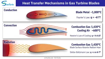
Thermal simulation software must account for three fundamental heat transfer modes:
- Conduction — Heat transfer through solid materials, governed by material thermal conductivity and temperature gradients
- Convection — Heat transfer by bulk motion of a fluid, including forced and natural convection in air or liquid
- Radiation — Electromagnetic heat transfer between surfaces, critical in vacuum environments and high-temperature applications
Real hardware often loads all three at once. A gas turbine blade, for example, sees conduction through the metal, convection from hot combustion gases and internal cooling passages, and radiation from flame and nearby turbine surfaces in the same operating point.
Steady-State vs. Transient Analysis
Thermal simulation offers two analysis modes:
Steady-state analysis calculates equilibrium temperature distribution after thermal loads stabilize. It answers: "What temperature will this component reach during continuous operation?" Use it when time history does not matter, such as an electronics enclosure under constant load or a power plant at steady output.
Transient analysis tracks time-dependent temperature changes as loads vary. It is essential for startup, shutdown, thermal cycling, or pulsed operation.
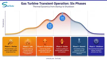
Gas turbines see one major thermal-fatigue cycle per flight—startup, idle, acceleration, and cruise. Simulating those transients reveals peak gradients, thermal lag, and fatigue damage that steady-state runs miss.
Types of Thermal Simulation Software and Core Technologies
Finite Element Analysis (FEA) Thermal Solvers
FEA divides solid structures into a mesh of discrete elements and solves heat-conduction equations at each node. It is strongest for temperature fields inside solid bodies, including:
- Printed circuit boards and semiconductor packages
- Metal housings and structural components
- Parts where conduction dominates over bulk fluid motion
FEA-based thermal solvers often include electrothermal coupling, which matters when electrical current generates heat in conductors or semiconductor junctions. When thermal conductivity depends on temperature, the FEA conductivity matrix varies with solution temperature, so the solver must iterate.
Computational Fluid Dynamics (CFD) Thermal Solvers
CFD models fluid flow and convective heat transfer by discretizing the Navier-Stokes and energy equations. Engineers rely on it when convection and flow paths drive the thermal result:
- Cooling-system and heatsink performance
- Airflow patterns and recirculation zones
- Aerodynamic heating and hot-gas mixing
The tradeoff is cost. One documented 30-million-cell run used 60 GB of memory and 60 seconds per iteration across 1,000 iterations. In return, CFD captures boundary-layer behavior and flow features that simpler models miss.
Coupled Multiphysics Simulation Platforms
Many thermal problems couple heat with stress, electrical behavior, and fluid dynamics. Coupled platforms solve those domains together:
- Thermal-structural: Temperature-driven expansion and thermal stress
- Thermal-electrical: Semiconductor performance loss under heat
- Thermal-fluid: Conjugate heat transfer between solids and coolant flow
Solving the domains together avoids errors from manually passing results between separate thermal and structural solvers.

Component-Based vs. System-Level Modeling Approaches
Choose the modeling scale based on the question you need answered:
- Component-level tools: Detailed 3D geometry and fine meshes for chips, boards, or turbine blades; best for local hot spots and steep gradients
- System-level tools: Full assemblies with enclosures, cooling loops, environment, and control logic; faster runs for mission cycles, design sweeps, and real-time studies
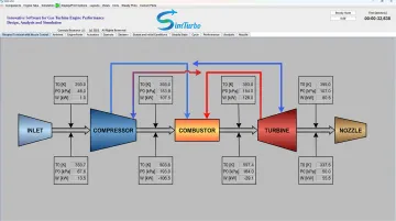
For gas turbines, a component-based architecture keeps the engine from becoming a black box. Inlets, compressors, combustors, turbines, nozzles, and shafts exchange flow, pressure, temperature, and power as the run progresses.
That setup lets you trace thermal coupling directly. Compressor discharge temperature can drive combustor heat release and turbine cooling demand without locked-in boundary conditions. Platforms such as SimTurbo use this style of component exchange for steady-state and transient engine studies.
Real-Time Simulation Capabilities
Some specialized platforms run thermal simulation in real time on standard hardware. Reduced-order models built from detailed 3D conduction analyses can solve 40,000+ times faster with useful predictive accuracy. Instead of waiting on overnight batch jobs, engineers can watch transient thermal response during design iterations, run interactive what-if cases, and check control logic against live thermal behavior.
Key Features to Look for in Thermal Simulation Software
Material Library and Property Management
Comprehensive material libraries with temperature-dependent thermal properties are essential for accurate simulation. Key properties include:
- Thermal conductivity (how easily heat flows through the material)
- Specific heat (energy needed to raise temperature per unit mass)
- Emissivity (surface radiation efficiency)
- Density and thermal expansion coefficients (mass and dimensional change with temperature)
When conductivity depends on temperature, the solver must update property values at each iteration. Evaluate how easily you can define custom materials and whether the software interpolates properties across wide temperature ranges. Gas turbines operating near 1,430°C require material data well beyond room-temperature handbooks.
CAD Integration and Geometry Import Capabilities
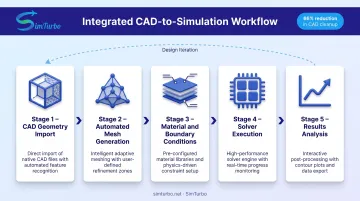
Direct CAD integration eliminates repetitive geometry cleanup and re-import errors. Moving from geometry to thermal setup in a single environment can cut CAD cleanup sharply—published workflow comparisons have reported reductions around 66%. Assess:
- Supported CAD formats (STEP, Parasolid, native formats)
- Automatic geometry simplification for thermal analysis (removing small fillets, holes that don't affect heat flow)
- Bi-directional updates when designs change
Time savings matter less than maintaining design fidelity. Geometry errors introduced during translation can invalidate results.
Meshing Automation and Quality
Mesh quality directly impacts solution accuracy and computation time. Adaptive refinement starts with a coarse mesh and estimates where error is high (typically around hot spots and steep gradients), then concentrates elements in those regions. Look for:
- Automated meshing with minimal manual tuning
- Refinement controls based on temperature gradient or heat flux
- Mesh-quality metrics and convergence-check tools
Even automated meshers require validation. Always perform mesh-convergence studies to confirm that further refinement doesn't change results significantly.
Gas Turbine-Specific Thermal Simulation Challenges
Extreme Temperature Gradients in Combustion Systems
Gas turbine combustors operate at temperatures exceeding 1,430°C while adjacent components must remain within material limits, often below 1,000°C. Specialized simulation tools must accurately model:
- Combustion heat release and flame patterns
- Liner cooling effectiveness through film cooling or transpiration
- Thermal boundary conditions at compressor discharge and turbine inlet
NASA research quantified local 1,600 K and 900–1,000 K regions coexisting in a single combustor-turbine interface. These gradients drive severe vane thermal stress and require coupled combustion-thermal-structural analysis to predict component life.
Turbine Blade Cooling and Heat Transfer Analysis
Modern turbine blades incorporate internal cooling passages with complex geometries: serpentine channels, impingement jets, and pin fins keep metal temperatures below material limits. Film cooling ejects cooler air through discrete holes, forming a protective layer over the hot-gas surface. Thermal simulation must simultaneously capture:
- Internal convection through cooling passages
- External aerodynamic heating from combustion gases
- Film-cooling effectiveness and mixing downstream of holes
- Conjugate heat transfer coupling solid blade temperatures with internal and external flows
Transient Thermal Behavior During Engine Operation
Gas turbines experience severe transients during startup, throttle changes, and shutdown. A single flight cycle includes startup, idle, acceleration, cruise, descent, and shutdown—each imposing different thermal loads. Transient simulation reveals:
- Thermal lag between gas-path temperature changes and metal response
- Pressure spikes before components reach equilibrium
- Compressor stall or surge risk when operating lines shift during acceleration
- Control-system response to maintain turbine-inlet-temperature limits
One documented transient analysis showed surge margin falling from 20–25% during normal operation to below 5% during an afterburner transient, requiring active fuel-flow and nozzle-area control to prevent compressor surge.
Component-Level Thermal Interaction Modeling
Gas turbines link compressors, combustors, turbines, and shafts so thermal behavior in one component affects the next. Component-based platforms model those couplings on a shared thermodynamic flow path instead of fixing arbitrary boundary conditions at each interface:
- Burner-entry temperature depends on compressor discharge conditions
- Combustor exit nonuniformity sends hot streaks into turbine vanes
- Turbine cooling-air extraction reduces compressor efficiency
- Shaft and secondary-flow paths carry heat and power between stations
SimTurbo: Specialized Gas Turbine Thermal and Performance Simulation
Those interaction problems are exactly what a component-based engine model is built to expose. SimTurbo, from Controls Research LLC, is a Windows-based gas turbine platform that pairs thermal analysis with real-time performance simulation for aerospace, power generation, and education.
Inlets, compressors, combustors, turbines, nozzles, and shafts exchange live flow, pressure, temperature, and power states as the run progresses, so the engine is never treated as a black box. The J85-GE-21 single-spool turbojet model has been validated against NASA Lewis Research Center test data to within ±2% on thrust, flow rate, temperature, and TSFC.
Engineers can work in steady-state cycle analysis or transient thermal simulation and watch:
- Temperature distributions and turbine-inlet-temperature shifts
- Thermal lag during startup, throttle bursts, and afterburner operation
- Real-time Temperature-Entropy and Pressure-Volume diagrams
SimTurbo runs on standard Windows PCs (8 GB RAM and a modern multi-core CPU). A 30-day free trial and university pricing cover professional seats, classrooms, labs, and research projects.
Industry Applications of Thermal Simulation Software
Aerospace and Defense Systems
Aerospace applications demand thermal simulation for engine components, aerodynamic heating on airframes at high speeds, and thermal management in spacecraft.
NASA guidance uses thermal models to compute electronic-box temperatures and heat flows from mounting interfaces to junctions. Those models support hot- and cold-case qualification and junction-limit checks. CFD validated against wind-tunnel and flight data provides ascent and reentry heating predictions for thermal-protection systems.
The vacuum environment in spacecraft eliminates convective cooling, leaving radiation and conduction as the only heat-rejection mechanisms. Accurate emissivity data and view-factor calculations are essential under those conditions.
Electronics Cooling and PCB Design
Miniaturization creates extreme thermal density. IGBT power modules in hybrid-electric vehicles generate 100–150 W/cm², while the U.S. Department of Energy targets 100 kW/L power density for vehicle electronics. Thermal simulation helps designers:
- Optimize component placement to avoid hot-spot overlap
- Design heatsink geometry and fin spacing for maximum airflow
- Evaluate forced-air or liquid-cooling systems before prototyping
- Predict junction temperatures and ensure components stay within ratings
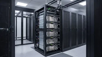
Data centers face similar challenges. With individual GPUs consuming 1,200 W, rack-level thermal management requires conjugate heat-transfer analysis coupling chip-package-board conduction with airflow and liquid-cooling loops.
Power Generation and Marine Propulsion
Gas turbines for power generation and marine propulsion operate continuously at high temperatures, where efficiency and reliability depend on managing thermal loads. Thermal simulation enables:
- Virtual prototyping of combustor liners and turbine vanes
- Evaluation of recuperator and regeneration cycles for efficiency improvement
- Transient analysis of startup, load changes, and shutdown
- Control-system validation before physical engine testing
For marine propulsion, system-level simulation couples gas-turbine thermal behavior with ship-wide energy networks, aftertreatment systems, and propulsion loads. SimTurbo supports these workflows with component-based modeling, real-time transient simulation, and control-system design tools validated against NASA engine test data.
Selecting the Right Thermal Simulation Software for Your Engineering Needs
Match Software Capabilities to Your Engineering Domain
Match the solver approach to the physics that actually drive your temperatures:
- Electronics cooling — Choose FEA-focused tools with electrothermal coupling, board-level modeling, and EDA workflow ties. Platforms such as Cadence Celsius couple thermal analysis with thermal stress and electrical performance.
- Fluid dynamics and cooling systems — Use CFD when airflow, liquid cooling, buoyancy, or film cooling sets the thermal field. Plan memory and runtime from mesh and physics needs; detailed conjugate heat-transfer runs can need 60 GB or more.
- Gas turbine performance and controls — Prefer component-based platforms that model compressor-combustor-turbine interactions without black-box assumptions. SimTurbo, for example, supports real-time transient thermal analysis and control-system validation on standard PCs.
- System-level and mission cycles — Apply reduced-order models for design sweeps, mission profiles, and hardware-in-the-loop work. Keep detailed 3D FEA or CFD for local hot-spot checks where gradients are steep.
Consider Integration with Existing Design Workflows
Software that integrates directly with your CAD, PLM, and analysis tools avoids file-translation errors and workflow disruptions. Evaluate:
- CAD import/export formats and bi-directional updates
- PLM integration for version control, traceability, and reuse of simulation data
- Automation capabilities for parametric studies and design optimization
- Cloud-based versus on-premises deployment and how each affects team collaboration
Direct geometry-to-simulation flow reduces repetitive setup and manual re-import. One case reduced CAD cleanup time by 66%, though solver time depends on model complexity, not just integration.
Evaluate Training Resources and Technical Support
Adequate training reduces time-to-productivity and improves simulation accuracy. Assess:
- Video tutorials covering fundamentals, workflows, and advanced features
- Verification examples with known solutions to validate your setup
- Solver documentation explaining governing equations, assumptions, and limitations
- User communities and forums for peer support
- Vendor technical support response times and availability
SimTurbo, for example, offers a video library on gas turbine fundamentals, simulation methodology, and user demonstrations, plus technical support for licensed users. No broad study quantifies training ROI across thermal tools, so judge support quality with a pilot problem from your own work.
Frequently Asked Questions
What is the best software for thermal simulation?
The best thermal simulation software depends on your domain. General-purpose tools like Ansys, Siemens Simcenter, and COMSOL cover broad multiphysics workflows, while Cadence Celsius targets electronics. For gas turbine engine thermal and performance analysis, component-based platforms like SimTurbo deliver real-time transient simulation validated within ±2% of NASA engine test data.
How does thermal simulation software work for gas turbine engines?
Gas turbine thermal simulation models heat transfer through combustion, turbine cooling, and component interactions with physics-based solvers. Component-based tools simulate inlets, compressors, combustors, turbines, and nozzles while tracking temperatures and cooling effectiveness in real time. Transient analysis captures thermal lag, pressure spikes, and surge-margin changes during startup and throttle changes.
What is the difference between CFD and FEA in thermal analysis?
FEA analyzes heat conduction through solids on a finite-element mesh, ideal for structural components, boards, and housings. CFD solves fluid flow and convective heat transfer for cooling systems and aerodynamic heating. Conjugate heat transfer couples both when solid and fluid temperatures must be solved together, as in turbine blade cooling.
Can thermal simulation software predict component failure?
Thermal simulation predicts temperatures, heat fluxes, and thermal stresses that show when components approach failure limits. Engineers compare results with material limits and feed temperature fields into stress analysis for thermal fatigue. It flags design risks before testing, but validation against test data and failure criteria is still required.
What industries benefit most from thermal simulation software?
Aerospace, electronics, automotive, power generation, and marine propulsion benefit most. These sectors manage high-temperature systems where predicting temperature, cooling flow, and thermal stress before hardware limits are exceeded cuts prototype cycles and field failures.