Engineers and students often struggle with IGVs for a simple reason: you can't see airflow. Vane angle, pre-swirl, stall margin, these are abstract until you watch them change in real time. This article breaks down what IGVs are, why turbines need them, how they work, and how simulation tools help engineers validate IGV control logic before touching real hardware.
Key Takeaways
- IGVs are adjustable vane rows at the compressor inlet that control airflow direction and volume
- Adjustable inlet vanes protect against compressor stall and surge while managing exhaust temperature
- Miscalibrated IGVs can measurably hurt efficiency and stability
- Platforms like SimTurbo let engineers model IGV-related control logic before physical testing
What Is an IGV in a Gas Turbine?
An inlet guide vane (IGV) is a row of airfoil-shaped vanes mounted at the compressor inlet of a gas turbine. Unlike a fixed strut, these vanes pivot together, driven by a common actuation ring, to change the angle and volume of air entering the first compressor stage.
Here's what separates an IGV from a basic throttling device:
- Butterfly valves just restrict flow, creating a pressure drop with no directional control
- IGVs turn the airflow, changing the incidence angle at the first rotor blade row
That turning effect, often called pre-swirl, aligns incoming air more closely with rotor rotation.
NASA testing on turbofan and turbojet compressors confirmed that closing IGVs produces a different aerodynamic response than simple duct throttling. The airflow, pressure ratio, and stability all shift in ways a plain valve can't replicate.
Where IGVs Show Up
IGVs aren't limited to one type of machine. Siemens Energy's SGT5-4000F, a heavy-duty industrial turbine, uses variable inlet guide vanes plus additional variable-pitch stages to improve part-load efficiency.
NASA has also studied variable-position IGVs on turbojet compressors and part-span versions on turbofan engines. The mechanical design and control logic differ between these applications, but the underlying job stays the same.
One detail engineers can't skip: IGVs are calibrated against a reference vane angle. The control system needs to know precisely where the vanes physically sit, not just where it commanded them to go. That distinction drives control accuracy, and we'll come back to it.
Why Gas Turbines Need Inlet Guide Vanes
IGVs earn their place in the compressor by doing three jobs at once.
1. Regulating airflow volume. As load drops, IGVs close to cut inlet air, matching flow to combustion needs without wasting compressor work.
2. Protecting against stall and surge. Closing the vanes lowers incidence at the first rotor and widens the compressor’s stable operating range.
3. Managing exhaust temperature. By controlling inlet airflow, IGVs keep turbine inlet and exhaust temperatures in the band needed for stable combustion and emissions compliance.
A 2024 compressor study in the Journal of Propulsion and Power found that increasing vane stagger trimmed pressure ratio and efficiency slightly, but widened the stable range by lowering first-rotor incidence. In plain terms: a small efficiency hit buys a much bigger safety margin.
A Real Numbers Example
NASA’s testing on a YTF34-F5 turbofan showed how dramatic vane closure can be. At full corrected fan speed, closing the part-span IGV from 0 to 50 degrees cut measured thrust from 31,700 N to 15,790 N—more than a 50% reduction—without fan stall. That is control authority a simple valve does not have.
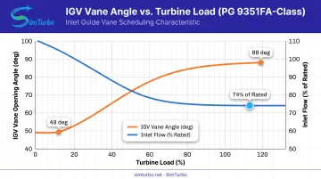
Modeling work on a PG 9351FA-class turbine showed IGV opening dropping from 88 to 49 degrees as load decreased, with inlet flow settling around 74% of rated once the vane hit its minimum angle. These are model-specific numbers, but they illustrate the range IGVs typically operate across.
How Inlet Guide Vanes Work
Picture a ring of vanes, each one pinned to a common actuation collar. When the actuator ring rotates, every vane changes pitch simultaneously and uniformly.
The mechanism breaks down like this:
- A hydraulic, electric, or pneumatic actuator drives the common ring
- The ring rotates all vanes to the same commanded angle
- Vane stagger changes both the turning of the airflow and the incidence angle hitting the first rotor blade
Why Pre-Swirl Beats Throttling
When IGVs angle the incoming air to match compressor rotor rotation, the rotor doesn't have to fight as hard against incoming flow. This reduces driver workload during turndown, something a butterfly valve can't offer since it only chokes flow rather than shaping it.
Beyond incidence control, vane angle also sets how much air the compressor swallows. Fully open vanes pass maximum flow for high-load operation. Closed vanes restrict flow for startup or low-load conditions, where less air is genuinely needed.
The tighter the calibration between commanded and actual vane position, the more predictable the turbine's response to load changes. Accurate position feedback is what keeps the engine stable instead of sluggish.
IGVs and Gas Turbine Control Systems
IGV actuators don't move on their own logic. They receive continuous commands from the turbine's control system, which tracks temperature, speed, and load in real time.
Common actuator types include:
- Hydraulic – the traditional approach, using high-pressure oil, pumps, filters, and servo valves
- Electro-hydraulic – blends hydraulic force with electric control precision
- Electric – GE's retrofit actuators use position control to manage airflow during starts and ramps, eliminating hydraulic oil dependency
Whatever the actuator type, the control loop still needs accurate feedback. GE's LM6000 documentation notes that LVDT position sensors, plus LPC inlet temperature and HPC discharge pressure, feed the loop that positions the vanes.
Small errors compound fast. A 2019 simulation study on the LM1600 modeled vane-schedule drift from worn linkages or failed bolts. A +6.5° drift cut simulated power by 15.38%; a -6.5° drift raised it by 14.75%, with shifts in efficiency and surge margin.
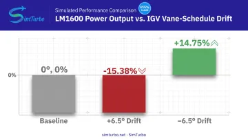
Those figures are simulation results, not fleet-wide guarantees. They still show why calibration accuracy maps straight to performance—and why IGV control logic (PID controllers, limiters, gain scheduling) should be modeled and validated before it touches real hardware. Tools built for that work, including SimTurbo's control components, let engineers stress vane schedules and limiters in software first.
Simulating IGV Behavior for Design and Validation
Testing IGV control logic on a physical turbine is expensive, slow, and risky if something goes wrong mid-transient. Simulation gives engineers a way to explore that behavior first.
Component-based simulation platforms let engineers model the compressor, combustor, turbine, and control components together, rather than treating the whole engine as a sealed black box. That distinction matters: black-box models hide the interactions between vane position, airflow, and downstream combustion stability that engineers actually need to see.
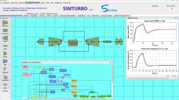
SimTurbo, built by Controls Research LLC, is one example of this approach. It's a Windows-based platform that runs on a standard PC and lets engineers:
- Build engine architectures using drag-and-drop components, including inlets, compressors, combustors, turbines, and shafts
- Watch real-time plots of transient throttle effects and control-law behavior
- Adjust variable-vane inputs and observe angle-control response on screen
- Export time-series data (RPM, EGT, thrust, SFC) to Excel or CSV for further analysis
- Connect exported "plant" responses to MATLAB/Simulink or Python for control validation work
SimTurbo's engine model has been validated against NASA Lewis Research Center test data for the J85-GE-21 turbojet, reporting accuracy within ±2% across thrust, flow rate, temperature, and TSFC. That's a solid baseline for engineers who want confidence in the underlying physics before layering in control-law experiments.
Aerospace, marine, and power-generation engineers use it to prototype control logic before hardware tests. University programs fold it into propulsion coursework, capstone projects, and lab instruction, often with vane-angle inputs and control-response plots built into the exercises.
For students, the 30-day free trial is a practical way to explore component-based modeling before committing to a paid tier.
Common IGV Problems and Maintenance Considerations
Even well-designed IGV systems degrade over time. Documented failure modes include:
- Actuator wear – bushings, thrust washers, and shafts subject to galling and corrosion
- Hydraulic leaks – external or internal cylinder leakage that reduces actuator authority
- Contamination – water ingress and particle buildup that degrade lubricant and corrode internal parts
- Miscalibration or drift – vanes failing to track commanded position due to worn linkages or failed hardware
Watch for these warning signs:
- Reduced power output without an obvious load change
- Slow or lagging vane response to control commands
- Unexpected control-system alarms tied to compressor performance
Routine calibration checks during planned outages catch most of these issues before they cause unplanned shutdowns. Pair lubricant analysis with physical inspection rather than relying on oil condition alone. Internal actuator damage often does not show up in oil properties first.
Frequently Asked Questions
What is an IGV on a gas turbine?
An IGV is a row of adjustable vanes at the compressor inlet that regulates incoming airflow. It protects against compressor stall and surge while helping manage exhaust temperature across load conditions.
What are the three main components of a gas turbine?
A gas turbine consists of the compressor, combustor, and turbine sections. IGVs sit at the compressor inlet, controlling the air that ultimately feeds combustion.
How do IGVs improve gas turbine efficiency?
IGVs pre-swirl incoming air to align with compressor rotor rotation, reducing driver workload. This improves part-load efficiency compared to simple throttling devices.
What happens if IGVs are miscalibrated?
Miscalibration can cause power loss, higher heat rate, and reduced surge margin. Simulation studies have shown that vane-position drift of just a few degrees can shift simulated power output by more than 14%.
Can IGV behavior be simulated before physical testing?
Yes. Platforms like SimTurbo let engineers model vane-related control logic and transient engine response on a standard PC before committing to physical test-cell validation.