This article explores how efficiency is defined and measured, which components and operating conditions have the greatest impact, and what optimization strategies deliver the most meaningful gains in real-world applications.
Key Takeaways
- Simple-cycle plants hit 30–40% thermal efficiency; combined-cycle units reach 60–64% by recovering exhaust heat
- Compression ratio, turbine inlet temperature, and ambient conditions drive most efficiency gains or losses
- Modern turbines run at 1,600–1,650°C with single-crystal superalloys and thermal barrier coatings
- Simulation lets engineers test design configurations and validate performance before physical builds
What Is Gas Turbine Efficiency?
Gas turbine efficiency describes how effectively an engine converts fuel energy into useful work. Two metrics drive the result: thermal efficiency (net power versus fuel energy input) and combustion efficiency (how completely fuel burns). Both shape engine performance, fuel use, and emissions.
Defining Thermal and Combustion Efficiency
Thermal efficiency is the ratio of useful work output to total energy supplied by the fuel, typically expressed as a percentage. For practical calculations, thermal efficiency equals net power divided by the product of fuel mass flow and the fuel heating value (LHV or HHV). This tells engineers how much of the fuel's chemical energy becomes mechanical shaft work or thrust.
Combustion efficiency measures how completely fuel burns inside the combustion chamber. Higher combustion efficiency means more fuel energy is released as heat, which raises engine performance and cuts unburned hydrocarbon emissions. In real engines, fuel quality, air-fuel mixing, and operating conditions still affect the final result.
The Brayton Cycle Foundation
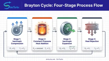
Gas turbines operate on the Brayton thermodynamic cycle, which describes the ideal energy-conversion process in four steps:
- Isentropic compression – Air enters the compressor and is compressed to higher pressure and temperature without heat loss.
- Constant-pressure heat addition – Fuel burns in the combustion chamber, adding energy at constant pressure.
- Isentropic expansion – Hot, high-pressure gas expands through the turbine, extracting work to drive the compressor and produce net output.
- Heat rejection – Exhaust gas releases remaining energy to the atmosphere.
The ideal Brayton efficiency formula is:
η = 1 - 1 / (PR^((γ-1)/γ))
where PR is the pressure ratio and γ is the specific heat ratio of the working gas. Higher compression ratios theoretically yield higher efficiency. Real engines still face practical limits from component performance, materials, and pressure losses.
Why Efficiency Varies by Configuration
How far that efficiency goes depends on engine configuration:
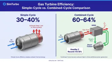
- Simple-cycle gas turbines achieve 30-40% thermal efficiency, discharging exhaust heat to the atmosphere.
- Combined-cycle plants capture exhaust heat in a heat recovery steam generator (HRSG) to drive a steam turbine, reaching 60-64% efficiency.
- Recuperated engines use exhaust heat to preheat compressor discharge air, improving simple-cycle efficiency without a separate steam cycle.
Efficiency also changes with load, ambient temperature, altitude, and specific design choices such as compression ratio and turbine inlet temperature.
Key Components and Their Role in Efficiency
Gas turbine efficiency depends on the integrated performance of three core components: the compressor, combustion chamber, and turbine. Each plays a distinct role, and their interactions determine overall system behavior.
The Compressor's Role in Efficiency
The compressor raises inlet air pressure and temperature, preparing it for combustion. Compressor efficiency directly impacts overall engine performance because compression consumes a significant portion of the turbine's power output. Poor compressor efficiency increases the work required, leaving less net power for useful output.
Two main compressor designs dominate:
- Axial compressors feature multiple stages of rotating and stationary blades, achieving high efficiency and large mass flow in a compact package, ideal for aircraft and large power plants
- Centrifugal compressors use a single or dual-stage rotating impeller to accelerate air radially, offering simplicity and high pressure ratios in smaller engines
A NASA rotorcraft compressor test achieved 85.5% polytropic efficiency at a 4.68 pressure ratio.
Combustion Chamber Design and Efficiency
The combustion chamber must balance competing objectives: achieve complete fuel burning for high combustion efficiency while controlling peak temperatures to manage nitrogen oxide (NOx) emissions. Effective fuel-air mixing, stable flame anchoring, and proper residence time are essential.
Design features include:
- Fuel injectors that atomize and distribute fuel evenly
- Swirlers and air-admission holes that promote mixing
- Liner cooling schemes that protect chamber walls
- Flame holders that stabilize combustion across operating conditions
The Turbine: Extracting Energy from Hot Gas
The turbine extracts work from the high-temperature, high-pressure gas stream exiting the combustion chamber. Turbine efficiency determines how much of the gas energy becomes useful shaft work. Blade design, materials, and cooling systems set the limits, because turbines operate at extreme temperatures. Modern designs reach 1,600–1,650°C.
NASA research shows that ceramic thermal and environmental barrier coatings increase permissible operating temperatures and reduce cooling requirements, supporting higher efficiency and lower emissions.
How Components Work Together as a System
Gas turbine efficiency is a system property shaped by how the components interact under load. The compressor and turbine must be properly matched: the turbine has to extract enough work to drive the compressor and auxiliary systems while still delivering net output. Mismatches cause off-design operation, increased fuel consumption, and reduced reliability.
Effective matching requires:
- Coordinated compressor and turbine maps
- Proper shaft speed and load distribution
- Sufficient surge margin to avoid compressor instability
- Control systems that maintain safe operating limits
Critical Factors Affecting Gas Turbine Efficiency
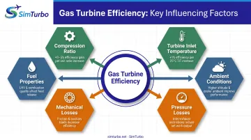
Six primary factors shape gas turbine efficiency in real-world operation: compression ratio, turbine inlet temperature, ambient conditions, pressure losses, mechanical losses, and fuel properties. Knowing how each one moves the needle helps engineers optimize designs and predict performance across varying conditions.
Compression Ratio and Its Impact
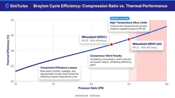
Higher compression ratios generally increase thermal efficiency under Brayton cycle theory, where ideal efficiency rises with pressure ratio (PR). Real engines still face practical constraints:
- Material limits – Higher pressure creates higher temperatures and mechanical stress
- Compressor work – More stages add weight, complexity, and friction losses
- Component efficiency – Actual compressor and turbine efficiencies reduce the theoretical gain
Mitsubishi's M501J turbine operates at a pressure ratio of 23 with 42% LHV efficiency. The proposed M501JAC design raised the ratio to 25 and efficiency to 44% LHV, though other design changes also contributed.
Turbine Inlet Temperature: The High-Temperature Challenge
Turbine inlet temperature (TIT) is one of the most influential efficiency drivers. Higher TIT enables greater energy extraction and improved Brayton cycle efficiency. Mitsubishi's M501JAC design achieved 1,650°C turbine inlet temperature using enhanced air-cooled combustion hardware, thicker thermal barrier coatings, and a higher-pressure-ratio compressor.
Challenges include:
- Materials science – Turbine blades must withstand extreme temperatures and mechanical loads using single-crystal nickel superalloys
- Cooling technology – Internal air passages, film cooling, and advanced coatings protect blades while minimizing cooling-air penalties
- Durability – High temperatures accelerate oxidation, creep, and thermal fatigue
Ambient Conditions and Environmental Effects
Air temperature, pressure, and humidity all affect gas turbine performance. A 2021 tropical plant study reported a 17% average power loss and 2.2% efficiency drop at 37°C compared to ISO conditions (15°C, 101.3 kPa). The same study cited losses of 0.1% thermal efficiency and 1.47 MW per °C above ISO.
Hot-day losses stack through the cycle:
- Lower air density at higher temperatures reduces compressor mass flow
- Reduced mass flow decreases fuel flow and turbine output
- Higher inlet temperature increases the work required for compression
Altitude also reduces air density, while humidity can slightly improve performance by increasing mass flow and reducing compression work.
Pressure Losses and Airflow Restrictions
Pressure drops through inlet systems, combustors, and exhaust systems consume available energy and lower efficiency. Every Pascal of pressure loss represents energy that cannot be converted to useful work.
Common sources include:
- Inlet filters, ducts, and anti-icing systems
- Combustor pressure drop from fuel injectors and flame holders
- Exhaust silencers, heat recovery equipment, and stack losses
Minimizing restrictions while maintaining necessary functions—filtration, noise reduction, emissions control—is an ongoing design trade-off.
Mechanical Losses and Parasitic Loads
Friction in bearings, seals, and gearboxes consumes power and reduces net efficiency. Auxiliary systems such as fuel pumps, oil pumps, hydraulic systems, and control electronics also draw power from the engine output.
While individual losses may seem small, they accumulate:
- Bearing friction increases with shaft speed and load
- Seal leakage reduces effective mass flow through the turbine
- Accessory drives and generators impose continuous parasitic loads
Fuel Properties and Combustion Quality
Fuel characteristics—heating value, composition, purity, and volatility—directly influence combustion efficiency and power output. Natural gas, diesel, jet fuel, and synthetic fuels each have distinct properties that affect engine performance.
Fuel quality specifications matter because:
- Heating value determines energy content per kilogram
- Composition affects flame temperature, emissions, and combustion stability
- Contaminants can cause fouling, corrosion, and reduced component life
These six drivers rarely move in isolation. Raising TIT or pressure ratio only pays off when materials, cooling, inlet/exhaust design, and fuel quality can support the change—cycle analysis is how engineers quantify those trade-offs before hardware is committed.
Understanding Efficiency Metrics and Real-World Performance
Engineers use several metrics to describe gas turbine efficiency and compare performance across different engines and operating conditions.
Heat rate expresses fuel energy input per unit of net electrical output, typically in Btu/kWh or kJ/kWh. Lower heat rate means higher efficiency. The U.S. Energy Information Administration reports 2024 average tested natural gas heat rates of 10,999 Btu/kWh for simple-cycle gas turbines and 7,548 Btu/kWh for combined-cycle plants.
Current efficiency benchmarks from production machines include:
- Simple-cycle: Siemens SGT-800 achieves 41.1% gross efficiency at 62 MW, with a heat rate of 8,759 kJ/kWh
- Aeroderivative: GE LM6000 VELOX PF+ Sprint reaches 41.0% net efficiency at 56.9 MW
- Combined-cycle record: Siemens SGT5-9000HL at Keadby 2 achieved 64.18% net efficiency and 849.45 MW, verified in May 2024
Advanced 3D-printed components at Keadby 2 optimized cooling passages and cut weight without sacrificing structural integrity—helping push that combined-cycle record.
Peak nameplate numbers only tell part of the story. Part-load efficiency matters because many gas turbines run below maximum output for extended periods. A 2020 peer-reviewed study found that compressor exergy loss share rises from 3% at full load to 9% at low load, while turbine losses remained near 7%. This explains why simple-cycle plants experience greater efficiency penalties at part load than combined-cycle configurations.
Methods to Improve Gas Turbine Efficiency
Several proven technologies and design strategies help engineers raise efficiency above baseline Brayton cycle performance.
Inlet Air Cooling Technologies
Reducing compressor inlet temperature increases air density, boosting mass flow and power output. Common approaches include:
Evaporative cooling uses wetted media or spray nozzles to cool inlet air through water evaporation. A peer-reviewed refinery gas turbine study reported 3% efficiency enhancement with evaporative media.
Fogging systems inject fine water droplets directly into the inlet airstream, providing rapid cooling with minimal pressure drop. Fogging works best in hot, dry climates.
Chilled water systems use mechanical refrigeration to cool inlet air below ambient temperature. The same refinery study found chillers deliver 15-20% output gain and 1-2% efficiency gain when exhaust energy is recovered, at higher capital cost than media or spray cooling.
Trade-offs include water consumption, space, maintenance, and climate-dependent effectiveness.
Combined Cycle and Heat Recovery
Combined-cycle configurations achieve the highest commercial gas turbine efficiencies by capturing exhaust heat that would otherwise be wasted. A heat recovery steam generator (HRSG) extracts thermal energy from 500-600°C exhaust gas to produce steam for a conventional steam turbine cycle.
Siemens reports combined-cycle efficiencies above 64%, compared to 30-40% for simple cycle. That is a 60-100% increase in useful work from the same fuel input. Combined cycle is the dominant choice for baseload power generation when capital investment and footprint can be justified.
Advanced Materials and Coatings
Materials science enables higher operating temperatures, which directly improve Brayton cycle efficiency. Key advances include:
Single-crystal superalloys eliminate grain boundaries that weaken conventional metals at high temperatures, allowing turbine blades to withstand higher stress and temperature.
Thermal barrier coatings (TBCs) provide an insulating layer between hot gas and metal surfaces. NASA tested hafnia/zirconia coatings on modified mullite with cyclic durability at 1,650°C.
Advanced cooling techniques use internal air passages, film cooling, and impingement cooling to keep blade temperatures below material limits while minimizing cooling-air flow penalties.
Design Optimization Through Simulation
Modern computational tools let engineers model and test design configurations before physical prototyping. Simulation cuts development time and cost while exploring trade-offs between efficiency, power output, emissions, and mechanical constraints.
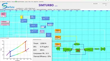
Platforms like SimTurbo enable engineers to evaluate:
- Compression ratio and turbine inlet temperature variations
- Component matching for compressor and turbine
- Transient behavior during startup, load changes, and emergency conditions
- Control system responses that maintain efficiency and avoid surge
Real-time visualization of thermodynamic cycles, component maps, and performance parameters surfaces optimization opportunities that would be difficult or expensive to test physically.
The Role of Simulation in Efficiency Optimization
Gas turbine simulation software helps engineers understand the complex interactions between components and operating conditions that determine efficiency. Rather than treating the engine as a black box, simulation platforms model individual components: compressors, combustors, turbines, nozzles, and control systems, and their thermodynamic relationships.
Virtual testing lets engineers explore design variations, operating strategies, and control schemes without the cost and time of building prototypes. They can adjust key inputs and watch the effects on performance:
- Compression ratios and turbine inlet temperatures
- Cooling flows and component geometries
- Efficiency, power output, fuel consumption, and surge margin
That feedback loop shortens the design cycle and lowers risk.
Simulation also helps students see how design changes affect the Brayton cycle. Interactive temperature-entropy and pressure-volume diagrams show compression, combustion, expansion, and heat rejection in real time. Students can experiment with:
- Recuperators and intercoolers
- Afterburners
- Variable-geometry components
Those exercises make efficiency trade-offs concrete instead of abstract.
Tools such as SimTurbo use component-based modeling for steady-state and transient analysis, with results validated against NASA J85-GE-21 engine test data within ±2% for thrust, flow rate, temperature, and thrust-specific fuel consumption. The same approach supports aerospace, power generation, and classroom work, with cloud access and a 30-day free trial for evaluation.
Frequently Asked Questions
What is considered good efficiency for a gas turbine?
Simple-cycle gas turbines typically achieve 30-40% thermal efficiency, with leading units like the Siemens SGT-800 reaching 41.1% gross at 62 MW. Combined-cycle plants reach 60-64%, with the Siemens SGT5-9000HL at Keadby 2 setting the current record at 64.18% net efficiency.
Are gas turbines more efficient than diesel engines?
Simple-cycle gas turbines (30-40%) generally lag large diesel engines (35-45%) in thermal efficiency. Combined-cycle plants (60-64%) beat diesel by a wide margin and are preferred for large-scale baseload generation, though application and size still decide the better fit.
Why do combined-cycle gas turbines achieve higher efficiency?
Combined-cycle plants capture waste heat from gas turbine exhaust to generate additional power through a steam cycle. The heat recovery steam generator (HRSG) extracts thermal energy that would otherwise be lost, effectively using the same fuel twice and raising overall plant efficiency from 30-40% to 60-64%.
How does ambient temperature affect gas turbine efficiency?
Higher ambient temperatures reduce air density, requiring more compressor work and decreasing both power output and efficiency. A tropical plant study found 17% average power loss and 2.2% efficiency drop at 37°C compared to ISO conditions (15°C), with losses of 0.1% thermal efficiency per °C above standard.
What is turbine inlet temperature and why does it matter?
Turbine inlet temperature (TIT) is the temperature of gas entering the turbine section after combustion. Higher TIT enables greater energy extraction and improved Brayton cycle efficiency. Modern turbines reach 1,600-1,650°C, with materials, coatings, and cooling systems setting the practical limit.
Can simulation tools help improve gas turbine efficiency?
Yes. Simulation software lets engineers model design variations, test operating conditions, and optimize component matching before building prototypes. Platforms like SimTurbo support rapid iteration on compression ratios, turbine inlet temperatures, and control strategies so teams can raise efficiency with less cost and risk.