Key Takeaways
- Axial displacement is the rotor’s longitudinal shift along the shaft axis relative to the casing
- Pressure thrust on rotor surfaces and momentum thrust from blade-row velocity changes drive the movement
- Uncontrolled displacement causes blade-to-diaphragm rubbing, thrust bearing failure, and unit trips
- Proximity probes and thrust bearing temperature sensors feed protection alarms and automatic trip logic
What is Axial Displacement in Turbines?
Axial displacement is the rotor's position along the shaft axis, measured relative to stationary casing components or a fixed reference point. Unlike radial vibration or differential expansion, axial displacement specifically tracks how far the entire rotor assembly moves longitudinally within the machine.
Engineers define a positive displacement as movement toward the driven equipment (generator or compressor), while negative displacement indicates movement toward the inlet or high-pressure section. This convention helps operators quickly interpret proximity-probe readings during startup, load changes, and trip events.
Why Tight Tolerances Matter
Rotating blades and stationary diaphragms or nozzle rings run with minimal axial clearances, often tenths of a millimeter, to hold efficiency and limit leakage. Even small rotor movement can close those gaps. Contact generates heat, accelerates wear, and can bend the rotor or damage blade tips, which then drives secondary vibration and forced outages.
The 60 MW steam turbine case documented at the 2018 Texas A&M Turbomachinery Symposium shows the risk in practice. Intermittent vibration spikes of 200–300% traced to exhaust-gland rubbing, casing distortion, and stuck support keys. Reduced axial float flagged the issue, but the root cause involved both rotor position and stationary-structure movement.
Axial Displacement vs. Differential Expansion
These two supervisory measurements are related but not the same:
- Axial displacement: rotor absolute position relative to the casing; protects the thrust bearing
- Differential expansion: change in axial clearance as rotor and stator heat or cool at different rates; protects blade-tip and seal clearances
Operators need both. Displacement tells you where the rotor sits; differential expansion tells you whether thermal growth is closing the gaps that keep the machine efficient and intact.
Operating Ranges and Alarm Logic
Acceptable displacement varies by turbine size, bearing design, and OEM clearance drawings. EPRI guidance on turbine supervisory instrumentation notes that alarm and trip setpoints are judgment-dependent and can differ even between apparently identical units.
Operators set cold and hot reference positions during commissioning, then track deviations from those baselines. Larger moves trigger stepped responses:
- Warning levels: increase monitoring and investigate drift
- High-high levels: automatic trip to avoid thrust-bearing or seal damage
The Physics Behind Axial Displacement
Axial forces on a turbine rotor come from two sources: pressure acting on rotor surfaces and momentum changes in the working fluid. Both drive force prediction and thrust-bearing design.
Pressure Thrust
Pressure thrust results from pressure differences acting over the cross-sectional areas of rotating components—discs, blade platforms, shaft steps, and seal faces. For a simplified uniform pressure distribution, the force is:
F_pressure = ΔP × A
where ΔP is the pressure difference and A is the effective axial area. In a multi-stage turbine, pressure drops from stage to stage, creating a cumulative force that pushes the rotor toward the low-pressure end. Interstage seals, balance pistons, and internal cavities all contribute pressure-loaded surfaces that must be included in the total.
Momentum Thrust
Momentum thrust arises from changes in fluid velocity as steam or gas accelerates through blade rows. NASA's thrust equation expresses the one-dimensional force as:
F = (ṁV)_exit – (ṁV)_inlet + A_exit(P_exit – P_ambient)
The first two terms represent the change in axial momentum flux; the last term accounts for exit-area pressure imbalance. For a turbine rotor, each stage changes fluid velocity and direction, contributing to the net axial load.
Combined Effect in Multi-Stage Machines
In a 10-stage steam turbine, each stage generates its own pressure and momentum components. The vector sum, accounting for direction, is the net force the thrust bearing must react. Stage admission, extraction flows, and seal leakage all modify local pressure and velocity fields, shifting that balance.
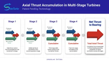
A 2025 CFD study of a full-scale regulating stage found blade-root hub thrust was the largest contributor and nearly linear with mass flow at partial load. Total thrust still declined as load dropped, so individual components do not all track operating changes the same way.
Why Thrust Direction Can Reverse
That net force is not fixed. Several operating and wear conditions can flip its direction:
- Startup thermal lag: HP stages heat and expand before downstream stages, so temporary pressure fields differ from steady state.
- Extraction-valve opening: HP exhaust pressure drops and HP-stage pressure ratio rises, shifting net thrust toward the HP end.
- Seal wear: Higher cavity leakage changes cavity pressure and the forces on disc faces.
NASA's 2003 turbine CFD work showed progressively worn seals raised cavity leakage from 3.5 to 8.1 (arbitrary units), redistributing cavity pressure over large disc areas and changing thrust.
Causes and Contributing Factors
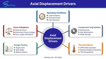
Axial displacement changes during operation reflect shifts in the forces and constraints acting on the rotor. Knowing which factor is driving a shift helps operators read trends early and act before clearances are at risk.
Operating condition changes:
- Load variations change steam or gas flow rate, pressure ratio, and temperature—shifting both pressure and momentum thrust
- Extraction flow changes (governor valve or extraction valve repositioning) modify interstage pressure distributions
- Sudden inlet-condition changes (pressure or temperature transients) unbalance forces until the machine reaches a new equilibrium
Component degradation:
- Thrust bearing pad wear or oil contamination cuts load capacity and allows more rotor movement under the same force
- Seal deterioration increases leakage, changing cavity pressures and the forces on rotating discs
- Blade or diaphragm damage alters flow paths and pressure distributions, shifting thrust magnitude or direction
Thermal effects:
- Differential thermal expansion: the lightweight rotor responds faster than the massive casing, so relative axial movement shows up mainly during startup and shutdown
A 2018 ASME study on steam turbine thermal limitations found that specific locations can become axially rub-limited during faster starts, even when overall clearances look adequate.
Design factors:
- Stage count and rotor geometry (disc diameters, blade heights) determine the magnitude of pressure-loaded areas
- Seal design and clearances control leakage rates and cavity pressures
- Balance-piston or dummy-piston sizing sets how much opposing force is available to offset main-path thrust
Measurement and Monitoring Systems
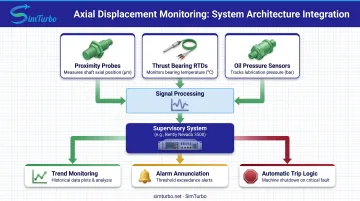
Real-time measurement of axial displacement and thrust bearing condition is the foundation of turbine protection. Modern systems combine proximity probes, temperature sensors, and integrated supervisory logic to detect problems before they cause damage.
Proximity Probe Systems
Non-contact displacement sensors, commonly called proximity probes or proximity transducers, mount near the thrust bearing and measure rotor position relative to a fixed casing reference. The Bently Nevada 3300 XL 11 mm system, for example, provides:
- 4.0 mm standard linear measurement range (approximately 0.5–4.5 mm target gap)
- 3.94 V/mm nominal sensitivity (±10%)
- ±0.10 mm linearity deviation
- 2.5 mm recommended nominal gap
These specifications describe the transducer's capabilities, not permissible rotor movement. EPRI recommends that axial-position probes be mounted within or near the thrust bearing assembly to accurately reflect rotor position under bearing load.
Thrust Bearing Temperature Instrumentation
Resistance temperature detectors (RTDs) or thermocouples embedded in thrust bearing pads detect overheating from excessive load or lubrication problems. Rising pad temperature often precedes measurable displacement changes, providing an early warning.
Differential oil pressure across the bearing measures the oil-film pressure that supports the load and adds another layer of bearing-health indication.
Integration with Turbine Supervisory Instrumentation
Displacement and temperature signals feed into machinery protection systems that compare real-time values against programmable alarm and trip setpoints. Bently Nevada's 3500 series, for instance, accepts proximity, temperature, and LVDT inputs and drives relay logic for alarm annunciation and automatic shutdown.
API 670 defines minimum protection-system scope for turbomachinery, including shaft axial position and critical bearing temperatures. Specific setpoint values remain with the OEM and site-specific protection philosophy.
Managing Axial Displacement in Design and Operation
Controlling axial displacement requires both sound mechanical design and disciplined operational monitoring. Engineers use thrust bearings, flow balancing, and real-time simulation to maintain rotor position within safe limits.
Thrust Bearing Systems
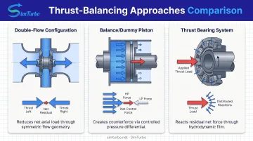
Hydrodynamic thrust bearings generate load capacity by dragging viscous lubricant through a converging clearance via relative motion between the rotating collar and stationary pads. As load or speed changes, film thickness adjusts to balance the applied force.
Tilting-pad designs are preferred for high thrust or variable alignment. Equalizing linkages transfer load through leveling plates so neighboring pads adjust dynamically, tolerate misalignment, and distribute load more evenly.
Directed lubrication, which supplies cooler oil directly to the film, improves thermal control and thrust capacity compared to flooded designs, where churning can limit performance. Proper sizing during design ensures the bearing can handle residual thrust under all operating conditions without excessive temperature rise or wear.
Design Features for Thrust Balancing
Double-flow configurations split the steam or gas path so fluid enters at the center and exits both ends, generating opposing axial forces that partially cancel. One documented opposed-flow steam turbine patent places HP and IP sections in opposition; the thrust bearing reacts only the residual difference.
Balance pistons or dummy pistons create opposing pressure forces by routing high-pressure fluid to one side of a sealed piston face and low-pressure fluid to the other. A reaction-turbine balance arrangement routes HP and IP exhaust pressures to respective balance-piston zones, generating a controlled counterforce that offsets main-path thrust. That counterforce cuts net bearing load.
Operational Monitoring Practices
Establish baseline axial-position values at rated load, part load, and no-load conditions during commissioning. Monitor trends during startups, load ramps, and extraction changes.
Correlate displacement with thrust bearing pad temperature and radial vibration:
- Rising temperature with increasing displacement suggests bearing overload
- Rising vibration with displacement may indicate rub or rotor bow
Respond to warning-level alarms by reducing load, checking extraction-valve position, and verifying bearing oil flow and temperature. High-high alarms require immediate load reduction or shutdown per plant procedures to prevent catastrophic blade or bearing damage.
During scheduled overhauls:
- Inspect thrust bearing pads for wear, scoring, or discoloration indicating overheating
- Measure axial clearances at blade tips and diaphragm faces; compare with design values
- Monitor wear patterns on seals and balance-piston surfaces
- Adjust bearing preload or shim clearances as needed to restore proper rotor positioning
- Replace worn seals to maintain designed cavity pressures and thrust balance
The Role of Simulation Tools
Engineers use specialized software to model axial forces during design, predict displacement under various scenarios, and validate control strategies before commissioning. Platforms that simulate gas turbine performance, including real-time thrust calculations, help aerospace and power engineers optimize designs and anticipate off-design behavior.
SimTurbo, for example, lets engineers model single-spool and dual-spool turbojet configurations, visualize transient thrust during startup and throttle changes, and export time-series data for further analysis. Validation of SimTurbo's J85-GE-21 model against NASA test data achieved thrust prediction accuracy within ±2%, which supports early-stage design and control-law checks.
Axial Flow vs. Radial Flow Turbines
Turbines are classified by the predominant direction of fluid flow relative to the shaft axis. This fundamental difference affects efficiency, size, and axial-thrust characteristics.
Flow Direction and Configuration
Axial-flow turbines have fluid moving primarily parallel to the shaft, passing through successive rows of stationary and rotating blades arranged circumferentially around the rotor. Each stage extracts energy by changing fluid velocity and pressure as it flows axially through the machine.
Radial-flow turbines have fluid entering or exiting perpendicular to the shaft. In a centripetal radial turbine, flow enters at the outer radius and turns inward toward the hub. In a centrifugal configuration, flow moves outward. Some designs use mixed flow, with radial inlet transitioning to axial outlet.
Axial Displacement Characteristics
Axial-flow turbines accumulate pressure and momentum thrust from each stage, with the vector sum determining net axial load. Multi-stage designs require robust thrust bearings and often incorporate double-flow sections or balance pistons to reduce bearing load.
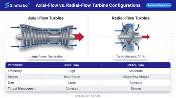
Radial turbines concentrate energy extraction in fewer stages. Pressure forces act primarily on the rotor disc face. In double-sided centripetal designs, opposing inlet flows can inherently balance axial forces. Single-sided radial turbines still generate significant axial thrust, so rotor-face pressure loading needs careful analysis.
Application Contexts
Axial turbines dominate large power generation, including steam turbines in combined-cycle and coal plants and industrial gas turbines. They offer higher efficiency at high mass flow rates and can add stages for greater pressure ratio.
Radial turbines are common in smaller applications such as turbochargers, auxiliary power units (APUs), and micro-turbines. Compact size, lower cost, and mechanical simplicity often outweigh peak efficiency. Their shorter flow path and fewer parts also simplify manufacturing and maintenance.
Frequently Asked Questions
What is axial displacement in a turbine?
Axial displacement is the rotor's longitudinal position along the shaft axis, measured relative to the stationary casing, caused by pressure and momentum forces from fluid flow through the turbine stages.
How do you calculate axial thrust in a turbine?
Sum pressure thrust (ΔP × A) and momentum thrust (ṁΔV) across stages for the net force. NASA's simplified form is F = (ṁV)_exit – (ṁV)_inlet + A_exit(P_exit – P_ambient); full work also needs stage data plus cavity and seal leakage.
What are the differences between axial and radial flow turbines?
Axial-flow turbines move fluid parallel to the shaft through blade rows and suit large power plants. Radial-flow turbines move fluid perpendicular to the shaft and fit compact uses like turbochargers. Axial machines build multi-stage thrust; radial designs concentrate it and can self-balance in double-sided layouts.
What is axial flow in a turbine?
Axial flow is fluid motion predominantly parallel to the turbine shaft, passing through successive stages of stationary and rotating blades that extract energy by changing velocity and pressure along the axial path.
What causes axial displacement to change during operation?
Load changes, extraction-valve repositioning, seal wear, thrust bearing degradation, and differential thermal expansion all alter the pressure and momentum forces acting on the rotor, changing its axial position.
How do thrust bearings control axial displacement?
Hydrodynamic thrust bearings generate opposing force through oil-film pressure, positioning the rotor and reacting residual thrust. Proper sizing and lubrication maintain rotor position within acceptable limits under all operating conditions.