While heat exchangers are ubiquitous in engineering systems, the specific mechanics of how PID controllers maintain optimal temperature setpoints—especially during transient operations—are often misunderstood. This knowledge gap leads to suboptimal tuning, temperature oscillations, and performance issues that compromise system efficiency and operational stability.
This guide explains how PID control operates within heat exchanger systems, covering the control logic, operational stages, tuning considerations, and real-world applications in gas turbine and power generation contexts.
Key Takeaways
- PID holds heat exchanger outlet temperature at setpoint by adjusting valve position or flow from the error signal
- P acts on present error, I clears steady-state offset, and D damps overshoot by responding to rate of change
- Common in gas turbine recuperators, intercoolers, feedwater heaters, and marine cooling circuits
- Simulation platforms let engineers design, tune, and validate PID strategies before hardware deployment
What Is Heat Exchanger PID Control?
Heat exchanger PID control is a closed-loop feedback system that holds a desired outlet temperature. It adjusts a control valve, pump speed, or bypass damper using continuous process measurements. The controller compares measured outlet temperature (process variable, or PV) to the desired temperature (setpoint, or SP) and calculates ongoing corrections.
The Problem PID Control Solves
Heat exchangers face constantly varying inlet conditions (flow rates, inlet temperatures, and heat loads) that would cause unacceptable temperature swings without automated correction. ISA identifies PID as the most common industrial closed-loop technology, especially for temperature control. Manual control cannot respond quickly or accurately enough to hold tight temperature tolerances during startup, shutdown, or load changes.
What Heat Exchanger PID Control Is NOT:
- Not open-loop control: Requires continuous feedback from temperature sensors
- Not simple on/off control: On/off action causes temperature cycling and mechanical stress
- Not cascade or feedforward alone: PID can still be combined with those advanced strategies
Why PID Remains the Industry Standard
PID balances performance, simplicity, and reliability. Unlike model predictive control, it needs no process model, uses little computing power, and has decades of field use across industries. Yokogawa documents industrial heat exchanger PID systems that hold outlet temperature by varying heating-medium valve position.
Configuration Variations by Heat Exchanger Type
PID control configuration varies depending on heat exchanger design:
- Shell-and-tube exchangers: Typically control hot-side or cold-side flow through modulating control valves
- Plate heat exchangers: May control both sides or use bypass control
- Gas turbine recuperators: Often use bypass valve control rather than direct flow manipulation to protect components during transients
- Feedwater heaters: Commonly use PI or PID control for level regulation in addition to temperature control
How Does Heat Exchanger PID Control Work?
Heat exchanger PID control runs a continuous four-stage cycle:
- Setpoint establishment and error detection
- Proportional-integral-derivative calculation
- Control signal transmission to the final control element
- Process response with feedback measurement
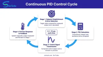
Each cycle typically completes in 0.1 to 10 seconds, depending on process dynamics and controller scan time.
Initiation and Error Detection
The control cycle begins when a temperature sensor, typically an RTD (Resistance Temperature Detector) or thermocouple, continuously measures the heat exchanger outlet temperature.
RTDs measure metal resistance change while thermocouples measure junction voltage. RTDs offer higher accuracy up to about 600°C; thermocouples cover wider ranges, in some cases up to 1,800°C.
The controller compares the measured Process Variable (PV) to the desired Setpoint (SP) and calculates error:
e(t) = SP - PV
Error sign and magnitude determine controller action:
- Positive error (PV below SP): Signals that more heating is needed
- Negative error (PV above SP): Signals that less heating or more cooling is required
- Error magnitude: Indicates how aggressively the controller should respond
When the controller is first enabled or switched from manual to automatic mode, most systems use bumpless transfer—setting initial output to the current valve position to prevent sudden process disturbances that could damage equipment or cause temperature spikes.
PID Calculation and Core Control Logic
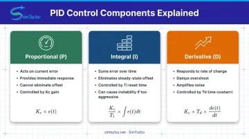
The PID controller combines three mathematical terms to calculate the optimal control output.
Proportional Term (P):
Multiplies current error by controller gain (Kc) for an immediate corrective response. Larger errors produce larger control actions and a fast first move. P-only control still cannot clear steady-state error; a small offset remains between setpoint and actual temperature.
Integral Term (I):
Accumulates error over time and corrects from that running total. Output keeps rising or falling until error reaches zero, removing the offset P-only control leaves behind. Reset time (Ti) sets how fast integral action builds. If integral action is too fast, it can destabilize the process.
Derivative Term (D):
Calculates the rate of change of the process variable and applies anticipatory correction. With time constant Td, derivative action damps overshoot and oscillation. It also amplifies measurement noise, so it is often applied only to PV rather than error to avoid "setpoint kick" (a sudden output spike when setpoint changes).
Standard PID Equation (Derivative on PV):
CO(t) = Bias + Kc[e(t) + (1/Ti)∫e(t)dt - Td(dPV/dt)]
Where:
- CO(t) = Controller output
- Bias = Initial or steady-state output value
- Kc = Proportional gain
- Ti = Integral time (reset time)
- Td = Derivative time
- e(t) = Error (SP - PV)
- dPV/dt = Rate of change of process variable
Engineers set tuning parameters (Kc, Ti, Td) through process testing or model-based correlations such as Ziegler-Nichols, Cohen-Coon, or Internal Model Control (IMC).
Control Signal Transmission and Actuation
The controller sends the calculated output to the final control element. The CO signal is typically a 4-20 mA current signal, standardized by ANSI/ISA-S50.1, or a 1-5 VDC voltage signal.
That signal drives a control valve actuator, variable-speed pump, or damper positioner, which adjusts flow through or around the heat exchanger.
Control Valve Characteristics:
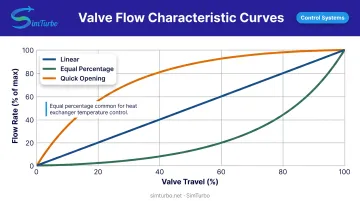
Valve flow characteristic should match the process gain behavior. Three main types exist:
- Linear: Flow proportional to valve travel
- Equal percentage: Equal travel increments produce equal percentage changes in existing flow coefficient (Cv)
- Quick opening: Large flow change for small initial travel
Equal percentage valves are commonly evaluated for heat exchanger temperature control because they can compensate for changing process gain across the operating range, though the optimal choice depends on installed gain, pressure drop, and rangeability requirements.
Practical Actuation Constraints:
- Output limits: High and low limits prevent controller from commanding impossible valve positions
- Anti-windup protection: Prevents integral term from saturating during sustained errors when valve reaches physical limits
- Valve travel limits: Define the physical range of control (typically 0-100%)
- Actuator speed: Limits how quickly the valve can respond to controller commands
Signal Conditioning:
Some systems require signal scaling or inversion depending on whether the controller is direct-acting (increasing output increases PV) or reverse-acting (increasing output decreases PV), which depends on heat exchanger configuration and whether the manipulated flow is heating or cooling.
Process Response and Measurement Feedback
After the control valve position changes, the heat exchanger responds with characteristic dynamic behavior. There is a dead time (transport delay) before temperature begins to change, followed by a first-order lag response as the heat exchanger reaches its new thermal equilibrium.
One documented shell-and-tube heat exchanger case identified a time constant (tau) of 36 seconds and dead time of 19 seconds under specific test conditions. Those values apply only to that 355 mm, four-tube laboratory exchanger at the tested flow rates. Actual time constants vary widely with thermal mass, flow, geometry, transport delay, valve behavior, and sensor assembly.
Closing the Feedback Loop:
The temperature sensor detects the process response and transmits the updated PV back to the controller, which calculates new error and repeats the control cycle continuously. Proper sensor placement at a mixing point downstream of the exchanger outlet and fast sensor response time are critical for stable control.
Interaction with Process Disturbances:
Changes in inlet temperature, flow rate, or heat load act as disturbances that create error, triggering the PID controller to make compensating adjustments automatically without operator intervention. Emerson notes that excessive loop-gain variation degrades dynamic performance, making the system oscillatory or unstable.
Control Loop Timing:
Controller scan time or sample rate should typically be 4-10 times faster than the process dead time—often 0.1-1.0 seconds for heat exchangers—to ensure the controller can track process changes without excessive lag or aliasing effects. Increasing scan time adds effective dead time and degrades performance.
Where Heat Exchanger PID Control Is Used
Gas Turbine Engine Applications
PID control is critical in several gas turbine heat exchanger applications:
- Recuperators recover turbine exhaust heat to preheat compressor discharge air and raise thermal efficiency. Bypass valve control often protects the core from thermal stress during startup and fast load changes.
- Intercoolers hold compressor interstage temperature in range to cut compression work. PID loops avoid temperatures cold enough for condensation or hot enough to hurt air density.
- Oil coolers keep bearing lubrication at the right viscosity and limit thermal breakdown. Large temperature swings shorten oil life and accelerate bearing wear.
Across these loops, PID control holds design-point efficiency and shields hardware during startup, shutdown, and load transients.
Power Generation and Industrial Process Applications
EPRI documents automatic feedwater heater level feedback systems where sensors transmit level information to PI or PID controllers that adjust drain-flow control valves. These systems maintain optimal heat transfer and prevent operational problems during transients.
Other critical applications include:
- Boiler economizers that preheat feedwater with flue gas
- Steam generator feedwater heaters using turbine extraction steam
- HVAC loops in critical facilities that need tight environmental control
- Chemical reactor cooling systems that remove reaction heat for safe temperatures
In each case, tight temperature or level control protects efficiency, product quality, and safe operating limits.
Simulation-Based Control Design and Validation
Before hardware commissioning, teams often prove heat exchanger PID strategies in simulation. Platforms such as SimTurbo include configurable Speed, Temperature, and Surge Margin PID components inside gas turbine system models, so temperature loops can be exercised with the rest of the plant.
Engineers typically use this workflow to:
- Design and validate PID logic against a simulated gas turbine plant
- Test response during startup, shutdown, throttle changes, and faults
- Tune Kc, Ti, and Td while watching temperature, speed, and surge-margin traces in real time
- Export transient data to CSV or Excel for post-processing
- Confirm protection margins before code reaches real hardware
Recuperated configurations can be modeled with heat recovery and temperature control in the loop. GE Vernova's Mark VIe DCS documentation describes a similar idea at plant scale: factory testing that pairs turbine control with plant simulation to cut commissioning risk.
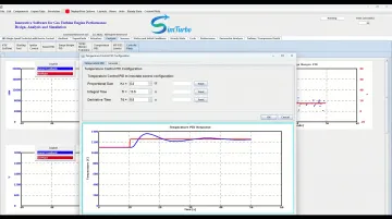
Catching unstable response, excess overshoot, thin protection margins, or bad fault handling in simulation is far cheaper than finding those issues in the field.
Conclusion
Heat exchanger PID control runs on continuous measurement-calculation-actuation-feedback cycles. Proportional action responds immediately to current error, integral action eliminates steady-state offset by accumulating past errors, and derivative action anticipates trends to cut overshoot and oscillation. Together, the three terms hold setpoint as process conditions change.
That logic is what helps engineers design stronger control strategies and troubleshoot performance issues systematically.
Proper PID design means choosing the right sensors and valves, tuning controller parameters through testing or simulation, and validating performance across the expected operating range. Simulation-based validation before hardware deployment improves reliability, shortens commissioning, and lowers the risk of failures in the field.
Apply these fundamentals, and you can deliver heat exchanger temperature control that holds steady when real process conditions shift.
Frequently Asked Questions
What is a PID used for?
A PID controller holds a process variable (temperature, pressure, flow, or level) at a setpoint by correcting from current error, accumulated past error, and the error trend. On heat exchangers, it typically trims valve position or flow to keep outlet temperature steady as inlet conditions and heat load change.
What are the two types of PID?
The two main forms are ideal (non-interacting), where P, I, and D act independently, and series (interacting), where the terms couple mathematically. Most industrial controllers use PI-D (derivative on PV only) so setpoint changes do not cause a sudden output spike, or setpoint kick.
What is a PID valve?
A "PID valve" is a control valve with an integrated PID positioner or smart actuator that takes a setpoint and closes position locally. Unlike a standard valve driven by an external controller’s position command, the onboard loop can cut dead time and speed response.
How do you tune a PID controller for a heat exchanger?
Identify process gain, time constant, and dead time from testing, then calculate Kc, Ti, and Td with correlations such as IMC, Ziegler-Nichols, or Cohen-Coon. A 2024 IEEE study compares these three methods for heat exchanger control; the best choice still depends on your dynamics and performance goals.
What causes PID oscillation in heat exchanger control?
Common causes are gain set too high (Kc), integral time too short (Ti), or derivative action that amplifies sensor noise. Valve stiction or deadband, sensor lag, and coupling with other loops can also drive sustained oscillation.
Can PID control be simulated before commissioning?
Yes. You can model exchanger dynamics and PID logic in software, then test setpoints and disturbances before touching hardware. That lets you refine tuning and catch response issues early, which shortens commissioning and lowers startup risk.