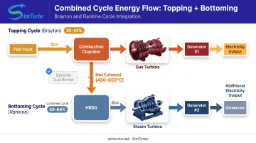
The topping cycle operates first in the thermodynamic sequence, combusting fuel at temperatures up to 1,426 °C and producing mechanical shaft work. Hot exhaust gases — still containing considerable energy at 450–650 °C — then flow to a heat recovery steam generator (HRSG) rather than being wasted, enabling the bottoming cycle to extract additional electricity.
This article explores topping cycle operational principles, thermodynamic foundations, components, efficiency benefits, and practical applications across utility, industrial, and marine sectors. You will also learn how simulation platforms such as SimTurbo model these systems for design, control validation, and engineering education.
Key Takeaways
- Topping cycle combusts fuel first for power, then sends waste heat to the bottoming steam cycle
- Modern H-class gas turbines run Brayton-cycle firing temperatures above 1,400 °C
- Combined cycles hit 50–64% thermal efficiency, roughly double simple-cycle performance
- Most plants pair a Brayton-cycle gas turbine with a Rankine-cycle steam turbine
- Units reach full load in under 30 minutes and run on natural gas or hydrogen blends
What Is a Combined Cycle Gas Turbine Topping Cycle?
A topping cycle is the first thermodynamic stage in a combined-cycle power plant. Fuel combustion drives a gas turbine that turns a generator to produce electricity. Exhaust gases exit the turbine at 450–650 °C—still hot enough to power a secondary steam cycle rather than being vented.
Thermodynamic Foundation
The topping cycle follows the Brayton cycle, a continuous-flow thermodynamic process with four stages:
- Compression — Ambient air is drawn in and pressurized, raising its temperature.
- Combustion — Fuel mixes with hot compressed air and burns at approximately constant pressure.
- Expansion — Hot, high-pressure gases expand through turbine blades, producing shaft work.
- Exhaust — Remaining gases exit and pass to heat recovery or the atmosphere.
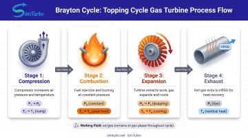
Unlike the Rankine cycle (which changes phase from water to steam and back), the Brayton cycle keeps the working fluid in gas phase throughout, enabling continuous high-temperature operation and rapid response to load changes.
Why "Topping" Cycle?
"Topping" refers to the cycle's position at the top of the temperature hierarchy. It receives chemical energy first and converts a portion into electricity. The remaining thermal energy flows downstream to the bottoming cycle.
By contrast, a bottoming cycle in an industrial plant extracts waste heat from a process (such as steel, glass, or cement production) and generates secondary power. Topping cycles prioritize electricity generation; bottoming cycles prioritize process heat with electricity as a byproduct.
How Does a Topping Cycle Work?
In a combined-cycle plant, the topping cycle is the gas turbine (Brayton) path: it burns fuel, makes shaft power, and leaves hot exhaust for the steam bottoming cycle. Energy moves through the machine in this sequence:
Chemical energy (fuel) → Thermal energy (combustion) → Kinetic energy (expanding gases) → Mechanical energy (rotating turbine) → Electrical energy (generator)
The Compression Stage
The compressor draws in ambient air and raises its pressure, often to ratios between 15:1 and 40:1. For example, the Siemens SGT5-8000H operates at a 21:1 pressure ratio. Higher pressure ratios improve thermal efficiency but demand advanced blade materials and cooling.
The Combustion Stage
Pressurized air mixes with fuel in the combustor. Continuous combustion occurs at 900–1,400+ °C. DOE research documents an H-class unit firing at 1,426 °C. Can-annular, annular, and can-type combustor designs balance performance, maintainability, and emissions control.
The Expansion and Power Generation Stage
Hot combustion gases expand through turbine blade rows, rotating the turbine shaft. Modern gas turbines produce 50–571 MW per unit. The shaft connects directly or through gearing to a synchronous generator. Exhaust typically leaves at 450–650 °C. DOE reports 593 °C in an advanced H-class case.
Heat Recovery for the Bottoming Cycle
Instead of wasting exhaust energy, a heat recovery steam generator (HRSG) captures it to produce steam. That steam drives a Rankine-cycle turbine, generating additional electricity. In the United States, 208 GW of 278 GW of CCGT capacity (75%) includes duct burners. Those burners can fire extra fuel in the HRSG, trading some efficiency for higher output or more operating flexibility.
Components and Configuration of a Topping Cycle System
Gas Turbine Components
Core components:
- Compressor — Usually axial-flow, multi-stage design; raises air pressure and temperature
- Combustor — Can, annular, or can-annular layout; mixes fuel and air, sustains flame
- Turbine — Multiple blade and vane stages; extracts energy from hot gas
Advanced cooling systems, including internal blade passages and film cooling, permit higher firing temperatures, directly improving efficiency and power density.
Fuel Systems and Options
Gas turbines accept multiple fuels:
- Natural gas — Most common, low sulfur and particulate emissions
- Liquid fuels — Diesel, kerosene, light fuel oil
- Synthesis gas — From coal or biomass gasification
- Hydrogen blends — GE lists 50 vol% H₂ capability for the 9HA with a pathway to 100%; other models vary
Fuel flexibility is model-specific. GE reports that its 9E fleet has operated on 52 different fuel types, but each turbine design has limits on composition, heating value, and combustion stability.
Generator and Power Output
The turbine shaft drives a synchronous generator, either directly or through a gearbox. Single-unit outputs range from approximately 50 MW to more than 400 MW, depending on model and configuration.
Configuration Options
Topping-cycle plants vary by shaft layout and whether they add duct firing:
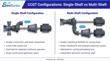
- Single-shaft — Gas turbine, steam turbine, and generator share one rotating shaft; simpler construction, lower cost, typically used for baseload
- Multi-shaft — Separate generators for gas and steam turbines; greater operational flexibility and easier maintenance, preferred for cycling or peaking duty
- Supplementary firing — Extra fuel burned in the HRSG duct boosts steam production and output. The U.S. Energy Information Administration (EIA) reports that 75% of U.S. CCGT capacity includes duct burners, though this adds fuel, emissions, and maintenance while reducing cycle efficiency
Efficiency and Performance Benefits of Topping Cycles
Thermal Efficiency Gains
Simple-cycle gas turbines reach 35–42% thermal efficiency. For example, the GE 6F.03 achieves 36.8% LHV in open-cycle operation. When exhaust heat is recovered, combined-cycle efficiency climbs to 50–64%. The GE 6F.03 exceeds 57% LHV in combined-cycle configuration, and large H-class plants can reach 64%.
Notable records:
- Bouchain, France — GE 9HA.01, 62.22% verified by Bureau Veritas in 2016
- GE 9HA.02 — Product capability announced at more than 64% in 2017
- Irsching Unit 4, Bavaria — Siemens SGT5-8000H, 60.75% net in May 2011
These efficiency gains result from extracting useful work across two temperature ranges: high-temperature combustion in the topping cycle and moderate-temperature steam generation in the bottoming cycle.
That same heat recovery also shapes how plants start, cost, and fit on a site.
Operational and Economic Advantages
- Rapid startup — H-class combined-cycle plants can reach full load in under 30 minutes, versus hours for coal or nuclear units
- Lower capital costs — EIA estimates $920.9/kW (2023 dollars) for a generic U.S. 627-MW single-shaft CCGT
- Smaller footprint — Higher power density cuts land requirements
These traits suit load-following and peaking duty, so CCGTs pair well with variable renewable generation.
Environmental Benefits
Natural gas CCGTs emit less CO₂ than coal-fired plants because of lower fuel carbon content and higher cycle efficiency. Other criteria pollutants stay low as well:
- Sulfur and particulate emissions are very low with natural gas
- NOx is managed with dry low-NOx combustors and selective catalytic reduction (SCR) to meet air-quality limits
Applications and Use Cases of Topping Cycles
Utility-Scale Power Generation
Topping cycles form the foundation of combined-cycle plants supplying baseload and intermediate electricity worldwide. EIA data shows 18.7 GW of U.S. CCGT capacity planned through 2028, with 4.3 GW already under construction as of June 2025.
Industrial Cogeneration and Marine Applications
Industrial cogeneration (CHP): Gas turbine topping cycles generate both electricity and process steam at facilities such as:
- Refineries and chemical plants
- Pulp and paper mills
- Food processors
- Universities and hospitals
Some DOE-documented cases achieve 63–71% total CHP efficiency.
Marine propulsion: Cruise ships employ COGES (Combined Gas Turbine Electric and Steam) arrangements. Celebrity Millennium, for example, uses gas-turbine generators with HRSG-derived steam. GE reported 20 LM2500+ and five LM2500 engines operating or planned in cruise-ship COGES and CODAG systems.
Integration with Renewable Energy
Gas turbine topping cycles provide rapid, dispatchable power when wind and solar output drops. NREL research notes that many older CCGTs were not designed for frequent cycling, so emissions, startup costs, and component wear must be managed when balancing variable renewables.
Across utility, industrial, and marine settings, teams often need to compare architectures before locking in hardware. With SimTurbo, engineers can build component-based gas turbine models—compressors, combustors, turbines, shafts, recuperators, and controls—and evaluate performance under the operating conditions each application demands.
Topping Cycle vs. Bottoming Cycle: Key Differences
| Dimension | Topping Cycle | Bottoming Cycle |
|---|---|---|
| Operational sequence | Fuel combusts first; electricity generated; waste heat follows | Heat source first (GT exhaust or process); waste heat recovered for power |
| Temperature range | 900–1,426 °C firing; 450–650 °C exhaust | Depends on heat source; steam typically 120–650 °C |
| Primary output | Electricity | Additional electricity from waste heat (process heat in industrial WHP) |
| Typical applications | Utility baseload, intermediate load, peaking | CCGT steam cycle; steel, glass, cement WHP plants |
| Integration | Paired with steam Rankine bottoming cycle in CCGT | Recovers GT exhaust or process heat; standalone WHP where no topping plant exists |
When Each Cycle Type Is Preferred
A topping cycle fits when electricity is the main product and you already have fuel supply plus a grid connection. Typical advantages include:
- Fuel flexibility across gas and liquid fuels
- Rapid startup for intermediate and peaking duty
- Straightforward scaling by unit size or count
- Lower capital cost per kilowatt than many steam-only plants
A bottoming or WHP cycle fits when high-temperature heat is already available on a steady basis—gas-turbine exhaust in a CCGT, or continuous process heat in heavy industry. Power then comes from heat you would otherwise reject, with little or no extra fuel.
Combined Cycle Integration
Most modern combined-cycle plants run a gas turbine (Brayton) topping cycle and feed its exhaust into a steam turbine (Rankine) bottoming cycle. The gas turbine makes power first; the HRSG and steam turbine convert remaining exhaust energy into more megawatts, pushing plant efficiency well above a simple-cycle gas turbine alone.
Frequently Asked Questions
What are the four stages of the Brayton cycle?
The four stages are: (1) compression of ambient air, (2) heat addition through fuel combustion at approximately constant pressure, (3) expansion of hot gases through the turbine producing shaft work, and (4) exhaust to the atmosphere or heat recovery system.
What is the difference between OCGT and CCGT?
OCGT (open cycle gas turbine or simple cycle) uses only the gas turbine to generate electricity and releases exhaust to atmosphere. CCGT (combined cycle gas turbine) adds a bottoming steam cycle to recover exhaust heat, roughly doubling efficiency from 35–42% to 50–64%.
What is the typical efficiency of a topping cycle?
Gas turbine topping cycles alone achieve 35–42% thermal efficiency (LHV basis). When exhaust heat is recovered in a combined-cycle configuration, overall plant efficiency reaches 50–64%.
Why are topping cycles more common than bottoming cycles in power generation?
Topping cycles start with dispatchable fuel, produce electricity as the primary product, and offer rapid startup, fuel flexibility, and lower barriers to deploy. Bottoming/WHP cycles need a continuous high-temperature waste-heat source, so they mainly fit specific industrial sites.
What fuels can be used in a gas turbine topping cycle?
Compatible fuels include natural gas (most common), liquid fuels (diesel, kerosene, light fuel oil), synthesis gas from gasification, biogas, and hydrogen blends. Hydrogen capability is model-specific; GE lists 50 vol% H₂ for the 9HA with a pathway to 100%, while other turbines have different limits.
How does simulation software assist in topping cycle design?
Simulation tools let engineers model thermodynamic performance, size components, predict efficiency across operating points, and validate controls before build. SimTurbo’s component-based approach supports configuring compressors, combustors, turbines, and controls for power, marine, and aerospace gas turbine design.