Introduction
Gas turbines face a core trade-off: more power output versus lower fuel burn. In simple-cycle machines, much of the thermal energy leaves with the exhaust—often above 500°C—so that heat never does useful work.
Recuperation recovers that waste heat to preheat compressed air before combustion. Thermal efficiency rises without exotic materials or turbine inlet temperatures beyond current metallurgical limits.
The recuperated Brayton cycle adds a heat exchanger (the recuperator) that moves energy from exhaust gas into compressor discharge air. Less fuel is then needed to reach the same combustor temperature. Those gains matter most where fuel cost and logistics dominate: marine propulsion, distributed power generation, and long-endurance rotorcraft.
This article covers Brayton cycle fundamentals, recuperation thermodynamics, design trade-offs, and real-world use across aerospace, marine, and industrial systems.
Key Takeaways
- Recuperation recovers turbine exhaust heat to preheat combustor inlet air, reducing fuel consumption
- Microturbines typically gain 10-14 percentage points in thermal efficiency with recuperation
- Pressure ratios of 3:1 to 5:1 deliver the best gains, when exhaust stays hotter than compressor discharge air
- Recuperators add weight, cost, and pressure drop that limit adoption in weight-sensitive applications
- Naval recuperated engines have cut fuel use by about 30%; microturbines reach roughly 33% electrical efficiency
What is the Brayton Cycle?
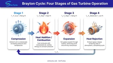
The Brayton cycle is the thermodynamic framework governing all gas turbine engines, from jet aircraft to industrial power plants. It consists of four distinct processes: compression of intake air, constant-pressure heat addition through combustion, expansion of hot gases through the turbine to extract work, and heat rejection as exhaust gases return to atmospheric conditions.
Ideal Versus Real Cycles
In the ideal Brayton cycle, MIT defines compression and expansion as reversible adiabatic (isentropic) processes, with heat addition and rejection occurring at constant pressure. Real gas turbines deviate from this ideal due to component inefficiencies, pressure losses through ducts and combustors, and non-ideal gas behavior at elevated temperatures.
The fundamental thermal efficiency equation for an ideal Brayton cycle is:
η = 1 - (1/r_p^((γ-1)/γ))
Where:
- η = thermal efficiency
- r_p = pressure ratio (compressor discharge pressure ÷ inlet pressure)
- γ = specific heat ratio (approximately 1.4 for air)
This relationship reveals a key insight: efficiency increases with pressure ratio.
Modern aircraft engines push that principle hard. GE's GE9X turbofan operates at a core pressure ratio of 27:1, while industrial turbines like the Siemens SGT-400 use ratios of 17:1 to 19.5:1.
Standard Cycle Applications and Limitations
Non-recuperated Brayton cycles power:
- Commercial and military jet engines
- Industrial gas turbines for power generation
- Simple-cycle peaking plants
The U.S. Department of Energy reports that simple-cycle gas turbines achieve 20-35% energy-conversion efficiency.
The primary limitation is exhaust heat. Stack gases often leave at 500-600°C, carrying away substantial thermal energy as lost work potential. Recuperation captures that waste stream and feeds it back into the cycle.
Understanding Recuperation in Gas Turbines
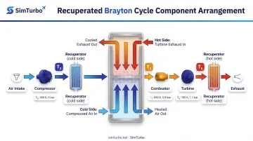
Recuperation (also called regeneration in some engineering texts) uses a heat exchanger to transfer thermal energy from hot turbine exhaust gases to compressed air entering the combustor. By preheating this air, the system requires less fuel to reach target turbine inlet temperatures, directly improving cycle efficiency.
The Thermodynamic Advantage
If compressed air enters the combustor at 350°C instead of 250°C, you need less fuel to reach a 1,200°C turbine inlet temperature. That lower fuel flow per unit power output improves thermal efficiency directly.
A 2017 Applied Energy review of micro gas turbines reports typical efficiency improvements from 16-20% without recuperation to approximately 30% with recuperation, a gain of roughly 10-14 percentage points.
The U.S. Department of Energy independently confirms this range, citing unrecuperated microturbines at 17-20% efficiency versus recuperated systems at 25-30%+.
Recuperator Effectiveness
Engineers quantify heat exchanger performance through effectiveness (ε), defined as the actual heat transfer divided by the maximum thermodynamically possible transfer:
ε = (T₃ - T₂)/(T₅ - T₂)
Where:
- T₃ = combustor inlet temperature (after recuperator)
- T₂ = compressor discharge temperature (before recuperator)
- T₅ = turbine exhaust temperature
Effectiveness ranges from 0 (no heat transfer) to 1 (theoretical maximum). Oak Ridge National Laboratory reports that counterflow recuperators generally must approach 85-90% effectiveness to achieve thermal efficiencies near 40% in microturbine applications.
The Pressure Ratio "Sweet Spot"
Recuperation delivers maximum benefit when turbine exhaust temperature significantly exceeds compressor discharge temperature, creating a useful temperature differential for heat transfer. This condition occurs at low-to-moderate pressure ratios.
ORNL research identifies a practical range of 3:1 to 6:1 pressure ratios for microturbines, with efficiency peaking around 4:1 to 5:1 under stated operating conditions.
As pressure ratio increases, compressor discharge temperature rises (following the Brayton equation), while turbine exhaust temperature falls. The two eventually converge to a point where recuperation offers minimal benefit.
High-pressure-ratio engines (above 15:1) typically see little advantage from recuperation because compressed air already exits the compressor hotter than the turbine exhaust.
Components of a Recuperated Brayton Cycle
Compressor
The compressor pressurizes intake air, raising both pressure and temperature as a function of pressure ratio and isentropic efficiency. In recuperated systems, designers often select lower pressure ratios (3:1 to 8:1) compared to simple-cycle turbines to maximize the temperature differential available for recuperation.
Lower pressure ratios also reduce the work fraction required to drive the compressor, leaving more turbine output available for useful power, at the cost of lower specific power density.
Recuperator (Heat Exchanger)
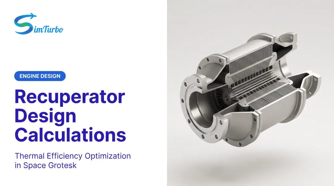
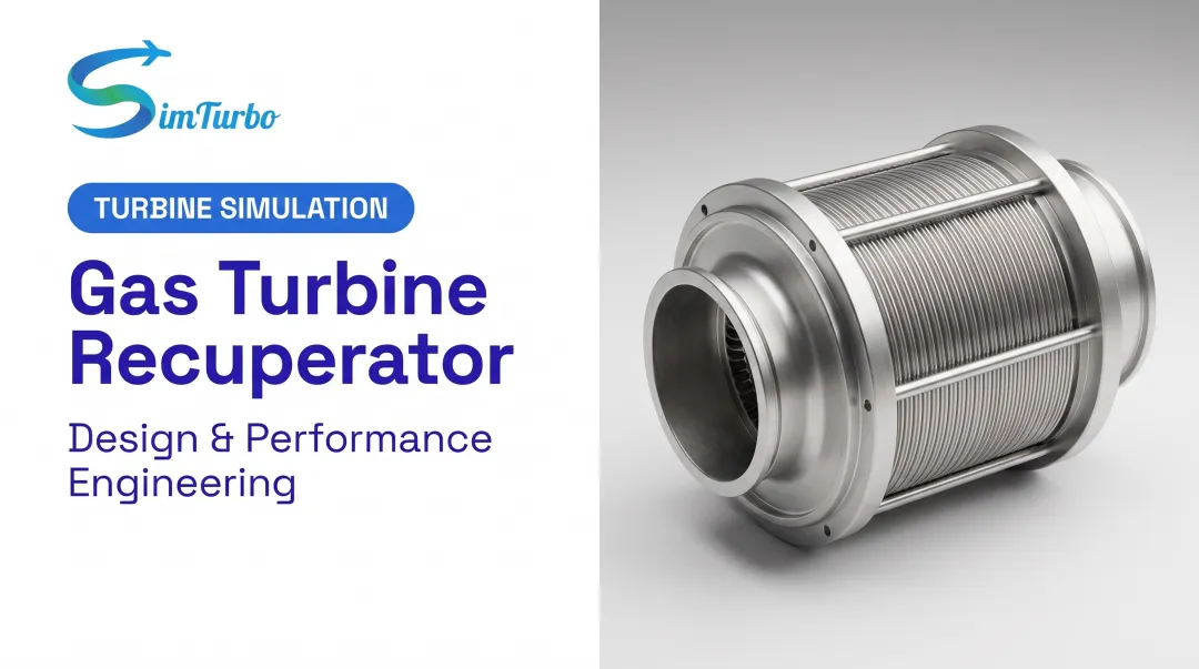
The recuperator is the defining component of the cycle. Common types include:
- Counterflow: hot and cold streams run in opposite directions to maximize temperature differential and effectiveness
- Crossflow: streams cross at 90°, favoring compact packaging with moderate effectiveness
- Plate-fin compact exchangers: alternating thin plates and corrugated fins, common in aerospace and microturbine work
ORNL classifies metallic microturbine recuperators as shell-and-tube, plate-fin, and primary-surface types, noting that shell-and-tube units are generally too bulky for small turbines. Counterflow plate-fin designs are favored when high effectiveness (85-90%) is required.
Material temperature limits set hard bounds on recuperator design:
- Stainless steel: below ~650°C
- Inconel (nickel-based superalloys): below ~800°C
- Ceramics: above ~870°C
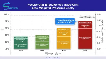
Higher effectiveness needs more heat-exchange area, which adds weight, volume, and pressure drop. NASA modeling found that raising effectiveness from 90% to 95% doubles heat exchanger area and mass, a penalty that may be unacceptable in weight-sensitive aerospace applications.
Combustor
Recuperation reduces the temperature rise required in the combustor because inlet air arrives preheated. This allows lower fuel flow rates for a given turbine inlet temperature, potentially reducing NOx emissions and extending combustor component life.
Turbine
The turbine extracts work from hot, high-pressure combustion gases to drive the compressor and produce net power output (or thrust in propulsion applications). Turbine inlet temperature remains a critical design constraint regardless of recuperation. Metallurgical limits still apply, and cooling strategies must manage blade temperatures.
At the same turbine inlet temperature, the lower pressure ratios used in recuperated cycles cut compressor work, so more of the turbine output becomes net power. Specific power density is still typically lower than in a comparable simple cycle.
Exhaust System
After passing through the recuperator, exhaust gases discharge to the atmosphere at significantly cooler temperatures than in simple-cycle turbines. Where a non-recuperated engine might exhaust at 550°C, a recuperated system may discharge at 300-350°C—visual confirmation that waste heat has been successfully recovered.
Thermodynamic Analysis and Performance
Efficiency Beyond the Simple-Cycle Model
The recuperated Brayton cycle efficiency depends not just on pressure ratio but also on recuperator effectiveness. While the simple-cycle relationship captures the ideal compressor-turbine trade-off, recuperation adds heat recovery that improves efficiency beyond the baseline prediction.
Engineers model recuperated cycles by adjusting standard Brayton analysis for reduced fuel input. The efficiency gain depends on:
- Temperature differential between turbine exhaust and compressor discharge
- Recuperator effectiveness
- Pressure losses through the heat exchanger
Performance Comparison Example
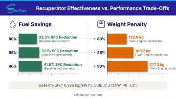
A Technical University of Munich study modeled a recuperated Allison 250-C20B turboshaft engine at pressure ratio 7.2:1 and 313 kW output. The baseline engine had a specific fuel consumption (SFC) of 0.396 kg/(kW·h). Adding an 80% effective recuperator reduced SFC to 0.268 kg/(kW·h), a 32.3% improvement.
That gain carried a substantial mass penalty for the twin-engine installation:
- 80% effectiveness: 2 × 61.4 kg
- 85% effectiveness: 2 × 84.6 kg
- 90% effectiveness: 2 × 138.6 kg
Mass rises nonlinearly as effectiveness targets climb, so weight-sensitive applications hit diminishing returns quickly.
Specific Power Trade-off
The U.S. Department of Energy reports that recuperated turbines produce approximately 10% less power than simple-cycle turbines at equal compressor pressure ratio and turbine inlet temperature. Pressure losses in the recuperator ducting and heat exchanger cut the pressure available for expansion work in the turbine.
Engineers must therefore balance thermal efficiency (favoring recuperation) against power density and specific output (favoring simple cycles).
Design Considerations and Trade-offs
Size, Weight, and Effectiveness
The core design challenge is the recuperator size-effectiveness trade-off. Higher effectiveness needs more heat-exchange surface area, which increases:
- Physical volume: Larger units occupy more engine bay space
- System weight: More material and structure to contain and support the exchanger
- Pressure drop: Longer, more restrictive flow paths increase losses on both hot and cold sides
NASA analysis confirms the nonlinear penalty: moving from 90% to 95% effectiveness doubles area and mass; reaching 99% doubles them again relative to 98%.
Pressure Drop Impacts
Pressure losses on both the hot exhaust side and cold compressed-air side directly reduce cycle efficiency. A recuperator that recovers 90% of available heat but incurs 5% pressure loss can deliver less net benefit than an 85% unit with only 2% loss.
The 2017 Applied Energy review specifies desired microturbine recuperator targets of >90% effectiveness with <3% relative pressure loss—a challenging combination requiring advanced compact heat exchanger designs.
Transient Operation Challenges
Recuperators add thermal mass and time constants that affect engine behavior during:
- Startup: The heat exchanger must warm before delivering efficiency benefits
- Shutdown: Residual heat requires careful management to prevent overheat
- Load changes: Recuperator thermal inertia delays response to power demand shifts
Engineers use simulation to model these effects and tune control strategies before hardware testing. Tools such as SimTurbo let designers run recuperated-cycle startup, shutdown, and load-following cases so they can manage recuperator temperature and pressure under dynamic conditions.
Economic Analysis
Recuperation increases capital cost but reduces fuel consumption, creating a payback calculation dependent on:
- Fuel price and escalation rate
- Annual operating hours
- Maintenance cost differential
- System lifetime
ORNL reports that recuperators typically account for 25-30% of total microturbine system cost.
A 2020 optimization study of a 200-kW counterflow plate-fin system reached 29.8% cycle efficiency and a 1.4-year discounted payback. Those results hinge on the study’s fuel-price and operating-hour assumptions.
Applications Across Industries
Aerospace and Aviation
Recuperated turboshaft and turboprop engines offer improved fuel efficiency for rotorcraft and general aviation, where mission duration and fuel load drive range and payload capability. However, the weight penalty limits adoption in high-performance applications where power-to-weight ratio is critical.
The Technical University of Munich helicopter study calculated 32-47% SFC improvement with 80-90% recuperator effectiveness, with mass penalties of 123-277 kg for a twin-engine installation.
A 2022 ASME analysis found that high-effectiveness units could require more than two hours of cruise to offset their weight through fuel savings. That trade-off confines them to long-endurance missions.
AIAA research still pushed the concept forward in 2020 with a recuperator design study for the Rolls-Royce M250-C30R/3 turboshaft, mapping pathways to practical helicopter use.
Marine Propulsion and Power Generation
Marine gas turbines benefit strongly from recuperation because weight is less critical than fuel efficiency and operating cost in naval vessels. The most prominent example is the WR-21 intercooled-recuperated engine developed for the U.S. and Royal Navies.
ASME documentation describes the WR-21 as a 21.6-MW (29,000 bhp) marine propulsion engine designed for 30% annual fuel savings versus simple-cycle engines.
Package characteristics included:
- Recuperator effectiveness: 88% at full power, 95% at low power
- Dimensions: 315 × 104 × 190 inches
- Weight: 120,000 lb
The Royal Navy became the first user of WR-21 in the Type 45 destroyer program, validating the technology at sea.
Industrial and Distributed Power
Recuperated microturbines (30-300 kW range) serve combined heat and power (CHP) applications where high electrical efficiency justifies added complexity. These systems are deployed in:
- Commercial buildings
- Industrial facilities
- District energy systems
- Renewable energy integration and hybrid-electric systems
Current Capstone Energy+ units include the C65 at 65 kW and 28% LHV electrical efficiency, and the C200S at 200 kW and 33% LHV electrical efficiency. Both reach up to 90% CHP efficiency by recovering exhaust heat for thermal loads, so the recuperator improves electrical output and usable heat in the same package.
Frequently Asked Questions
What is the purpose of a recuperated cycle in a gas turbine?
Recuperation improves thermal efficiency by recovering waste heat from turbine exhaust to preheat combustor inlet air, reducing fuel consumption. This heat recovery can boost microturbine efficiency from the high teens into the 28-33% range.
What is the Brayton cycle and how does it work?
The Brayton cycle is the four-stage process that governs gas turbines: compression, heat addition (combustion), expansion through the turbine, and heat rejection. Efficiency rises with higher pressure ratio and turbine inlet temperature.
What are the main advantages of a recuperated Brayton cycle?
Recuperated cycles deliver 10-14 percentage-point efficiency improvements in microturbines, reduce fuel consumption by 30-47% in optimized applications, and can lower emissions compared to simple-cycle turbines. In CHP systems, waste heat can still be recovered from cooler exhaust for additional benefit.
Why isn't recuperation used in all gas turbines?
Recuperators add weight, complexity, cost, and pressure drop, making them economically viable only where fuel savings justify system complexity. High-pressure-ratio engines (above 15:1) see little benefit. Compressor discharge temperatures already approach or exceed exhaust temperatures, so little heat remains to recover.
At what pressure ratio is recuperation most effective?
Recuperation provides maximum benefit at low-to-moderate pressure ratios of 3:1 to 5:1, where turbine exhaust temperature significantly exceeds compressor discharge temperature. Beyond 6:1, the temperature differential shrinks, reducing recuperator effectiveness and net efficiency gain.
How does recuperator effectiveness impact cycle performance?
Higher effectiveness transfers more waste heat to compressed air and improves thermal efficiency, but it needs larger, heavier heat exchangers with more pressure drop. The trade-off between fuel savings and weight, cost, and pressure-drop penalties sets the right design for each application.
Interested in exploring recuperated gas turbine cycles through simulation? SimTurbo is a component-based platform for designing, simulating, and analyzing recuperated Brayton cycles, including transient startup and shutdown.
Engineers and students can model recuperator setups, review thermodynamic performance in real time, and export data to MATLAB, Excel, or Python. Try the free 30-day trial or schedule a demo to see it in action.