Designing these components demands expertise across multiple engineering disciplines. Aerodynamicists shape airfoils to redirect gas flow efficiently. Materials scientists develop nickel-based superalloys and ceramic coatings that resist extreme heat. Thermal engineers create intricate internal cooling networks with passages and holes measured in fractions of a millimeter. Manufacturing specialists control solidification processes at the atomic level to eliminate grain boundaries that cause fatigue cracks.
This article examines how engineers integrate these disciplines to create turbofan blades that power modern aviation.
Key Takeaways
- First-stage blades see gas near 1,700°C, hundreds of degrees above the alloy melting point
- Single-crystal casting removes grain boundaries and boosts creep and fatigue life
- Film-cooling holes (0.3–0.5 mm) shield blades using about 2.75% of core airflow per stage
- Simulation flags aero, thermal, and structural risks before any hardware is cut
Blade Anatomy: Root, Shroud, and Airfoil
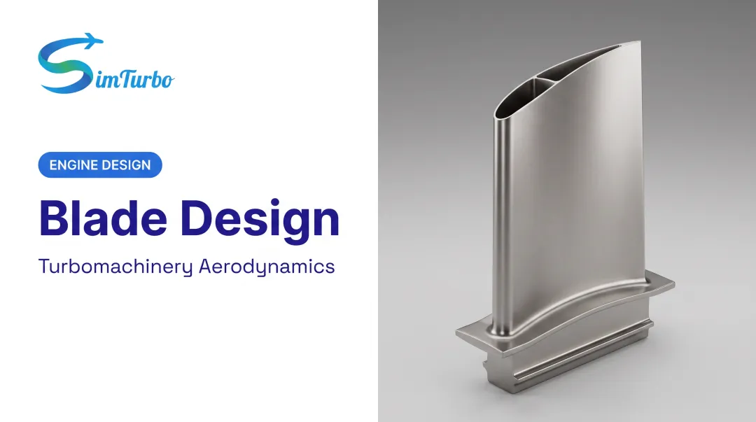
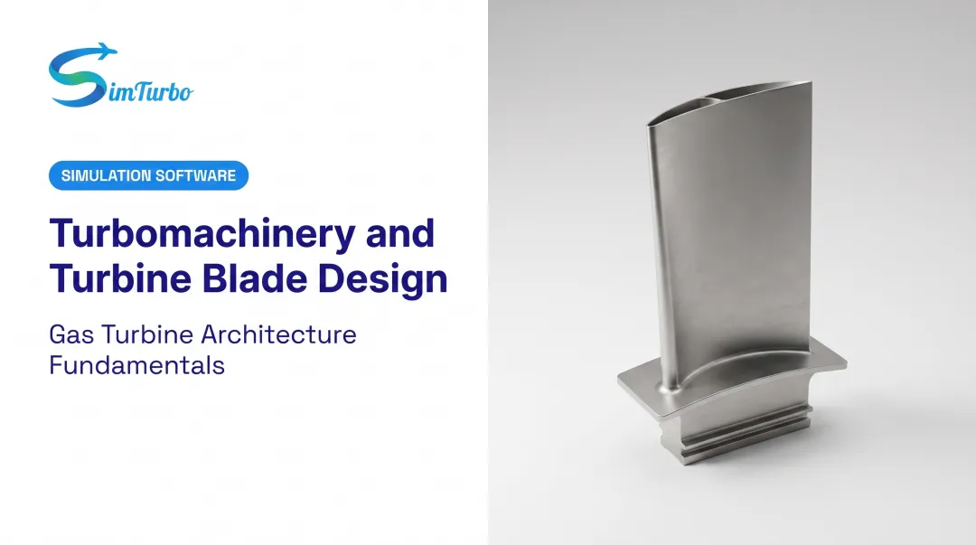
Every turbofan blade has three integrated sections that work together under extreme conditions. The root anchors the blade to the rotating disk and transfers loads. The airfoil is the aerodynamic surface that extracts energy from hot gases.
The shroud seals the blade tip to limit efficiency-robbing gas leakage. How these sections share load, heat, and flow paths drives the rest of the design.
The Root: Securing Blades Under Extreme Forces
The blade root must withstand enormous centrifugal forces generated by high-speed rotation. Fir-tree or dovetail attachment designs lock the blade into precision-machined slots on the turbine disk. These geometries distribute centrifugal loads across multiple contact surfaces, preventing the blade from pulling free during operation.
Single-crystal blade roots require special attention. NASA research confirms that contact-stress analysis is essential for these attachments because the crystallographic structure affects how stress concentrates at contact points. Engineers must account for both mechanical loading and thermal expansion throughout the operating envelope.
The Airfoil: Converting Thermal Energy to Mechanical Work
The airfoil's curved profile redirects high-velocity combustion gases to create rotational force on the turbine disk. Unlike aircraft wings with constant cross-sections, turbine airfoils twist continuously from root to tip. That three-dimensional shape matches gas velocity, temperature, and pressure changes across the blade height.
Four key surfaces define aerodynamic performance:
- Leading edge: where hot gas first contacts the blade
- Trailing edge: where gas exits to the next stage
- Pressure side (concave): higher static pressure
- Suction side (convex): lower static pressure
The pressure difference between these surfaces generates the force that drives the turbine.
The Shroud: Minimizing Tip Leakage Losses
Gas naturally wants to bypass blade tips by flowing over the top from the high-pressure side to the low-pressure side. Shrouds—either integral to the blade or separately attached—reduce this leakage by creating a tighter seal with the engine casing.
NASA research on gas turbine tip clearance demonstrates that clearance control significantly impacts efficiency. In one documented experiment, a 6.8% increase in clearance-to-passage-height reduced efficiency by approximately 20%. Even a 10-mil clearance reduction can improve mission efficiency by as much as 1% in some gas turbine applications.
Materials and Material Science
The Evolution from Conventional Alloys to Superalloys
Early jet engines of the 1940s-1950s used conventional nickel alloys with limited temperature capability. NASA's 1970 materials review documented that nickel/cobalt superalloy rotor blades operated only slightly above 1,800°F at that time—a severe constraint on engine performance.
Modern nickel-based superalloys raised turbine temperature limits by adding elements that strengthen the material at high temperatures:
- Chromium for oxidation and corrosion resistance
- Cobalt for high-temperature strength
- Rhenium for creep resistance and higher temperature capability
With those additions, blades survive gas-path temperatures that earlier alloys could not sustain.
Single Crystal and Directionally Solidified Blades
Traditional polycrystalline metals contain grain boundaries—interfaces where crystal structures meet. These boundaries represent weak points where cracks initiate and creep occurs at high temperatures. Eliminating them transforms blade durability.
Three casting structures offer progressively better performance:
| Structure | Grain boundaries | Advantage |
|---|---|---|
| Polycrystalline | Random, throughout the blade | Established manufacturing |
| Directionally Solidified (DS) | Aligned parallel to blade axis | Improved creep resistance along primary stress direction |
| Single Crystal (SC) | None—entire blade is one crystal | Maximum creep and fatigue resistance |
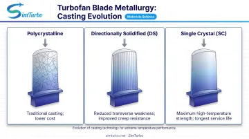
Howmet's foundry process grows single-crystal aeroengine airfoils by carefully controlling solidification. Research on directional solidification shows that casting withdrawal rates of 3-5 mm/min produce optimal results in DD9 alloy. Above 5 mm/min, defects like stray grains become more likely.
Thermal Barrier Coatings (TBCs)
Ceramic thermal barrier coatings add an insulating layer that cuts the heat reaching the metal substrate. The most common TBC material is 7-percent yttria-stabilized zirconia (7YSZ), which NASA's 2018 coating history identifies as the baseline ceramic used in every new aircraft and ground-power turbine engine at that time.
TBCs serve multiple protective functions:
- Create a thermal gradient that keeps metal cooler
- Protect against oxidation in high-temperature oxygen-rich environments
- Shield against hot corrosion from fuel contaminants
- Extend blade service life between overhauls
Common Turbofan Blade Material Examples
NASA/Pratt & Whitney Energy Efficient Engine documentation provides specific material benchmarks from civil turbofan programs:
- SC 2000: E3 flight propulsion system blade material with higher temperature capability than first-generation PWA 1480
- PWA 1480: First-generation single-crystal alloy used in the E3 integrated-core blade; set the commercial turbofan baseline
- PWA 1484: NASA strength testing showed peak strength near 760°C (1,400°F) and reduced strength at 871°C (1,600°F)
- CMSX-4: Aerospace single-crystal alloy with thermomechanical fatigue data across 750–1,050°C for design validation
Cooling Technologies: Managing Extreme Temperatures
Why Cooling is Essential for Modern Turbofan Performance
Rolls-Royce engineering documentation states that combustor exit gas reaches 2,000 K (1,700°C)—several hundred degrees above blade material melting points. Without sophisticated cooling, blades would fail within minutes.
Both internal and external cooling systems keep blade temperatures within safe limits while allowing engines to operate at the high temperatures that maximize efficiency and thrust.
Internal Cooling Methods
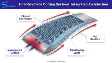
Convection cooling routes compressed air through serpentine passages cast inside the blade. These passages feature turbulence promoters—small ribs or pins that disrupt smooth airflow, increasing heat transfer from the blade material to the cooling air.
Multiple passes allow the coolant to absorb heat progressively as it travels from root to tip. Where convection handles general blade cooling, impingement cooling targets the highest-heat areas with focused jets. High-velocity air streams shoot through small holes in internal walls, impinging directly on the backside of the leading edge or other critical hot spots. This technique delivers intense cooling exactly where thermal loads are greatest.
External Cooling: Film Cooling
While internal passages cool the blade structure, external film cooling shields the outer surface from direct gas exposure.
Film cooling creates a protective blanket of cooler air over the blade surface. Cooling air exits through precisely angled holes (typically 0.3-0.5 mm diameter) drilled through the blade wall, forming a thin film layer that insulates the surface from the hot mainstream gas.
Measuring Film Cooling Effectiveness
Engineers measure film cooling effectiveness using:
η = (T∞ - Taw) / (T∞ - Tc)
Variable definitions:
- T∞ = mainstream gas temperature
- Taw = adiabatic wall temperature (blade surface with cooling)
- Tc = coolant temperature
NASA film cooling research validated this metric through computational fluid dynamics and experiments across blowing ratios of 0.5-2.0, using centerline temperature measurements to compare predictions with test data.
Cooling air requirements are substantial. The Pratt & Whitney/NASA E3 rotor blade design requires 2.75% of core engine airflow for blade cooling—a significant quantity that represents an efficiency penalty since this air bypasses the combustion process.
Advanced Cooling Techniques and Design Trade-Offs
Pin fin cooling fills narrow trailing-edge cavities with arrays of small cylindrical pins. These pins increase surface area for convection cooling in regions too thin for serpentine passages.
Transpiration cooling concepts allow coolant to seep through porous blade materials, creating an extremely uniform protective layer. This remains largely experimental due to manufacturing challenges and material durability concerns.
Every cooling system involves trade-offs. Extracting air from the compressor for blade cooling reduces overall engine efficiency. More cooling air means better blade protection but lower thermodynamic performance. Optimal blade design balances thermal protection, aerodynamic efficiency, and manufacturing feasibility.
Aerodynamic Design Principles
Airfoil Shaping for Optimal Gas Flow
Turbine airfoil profiles redirect gas flow with minimal energy loss, applying principles similar to aircraft wing design but adapted for the hot, high-speed environment. Engineers optimize entrance and exit angles to match gas flow directions at each stage, ensuring smooth flow attachment and minimal separation losses.
Commercial turbofan optimization research varied key geometric parameters at root, mid-span, and tip sections:
- Inlet and exit metal angles
- Blade camber (curvature)
- Circumferential lean
- Stagger angle
- Leading and trailing edge positions
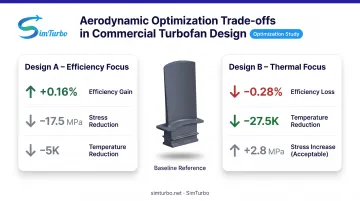
One design achieved +0.16% efficiency improvement with -17.5 MPa lower peak stress and -5 K reduced peak temperature. An alternative design lowered temperature by -27.5 K but sacrificed 0.28% efficiency. Competing gains like these are normal in blade design.
Managing Three-Dimensional Flow Effects
Unlike two-dimensional airfoils, turbine blades operate in a complex three-dimensional flow field. Gas velocity and temperature vary dramatically from blade root (near the hub) to blade tip. Blade twist and circumferential lean address these variations by optimizing the airfoil shape at each span location.
A 2024 aeroengine optimization study demonstrated that refined blade geometry reduced first-stage rotor energy loss by 14.57% and eliminated suction-side trailing-edge flow separation near the tip. The same optimization increased maximum von Mises stress by 20.38%, so every aerodynamic gain still needs structural sign-off before the shape is viable.
Crystal Orientation and Mechanical Performance
How far those aerodynamic shapes can go depends on the alloy and its grain structure. Howmet's casting documentation notes that single-crystal airfoil grains are aligned with the primary centrifugal force direction, which limits deformation under load and raises temperature capability and service life.
Single-crystal alloys are anisotropic: strength varies with direction. Aligning the strongest crystal axis with the dominant stress maximizes durability and supports more aggressive airfoil shapes than conventionally cast materials can survive.
Design Process and Simulation
The Modern Blade Design Workflow
Turbofan blade development follows a systematic progression:
- Requirements definition - Specify operating conditions, life targets, and performance goals
- Conceptual design - Establish basic airfoil shape, cooling scheme, and material selection
- Detailed CAD modeling - Create precise three-dimensional geometry
- Simulation and analysis - Predict aerodynamic, thermal, and structural behavior
- Prototyping - Manufacture test blades using production-intent processes
- Testing - Validate predictions through rig testing and engine trials
- Iteration - Refine design based on test results
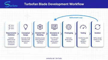
Iteration between simulation and physical testing remains essential. Simulations guide design but cannot capture every real-world effect. Test data validates models and reveals issues that inform the next design cycle.
Computational Analysis in Blade Development
Engineers rely on two primary simulation tools:
Computational Fluid Dynamics (CFD) analyzes gas flow around the blade. CFD predicts:
- Aerodynamic efficiency and loss mechanisms
- Surface pressure distribution
- Temperature fields in the hot gas
- Velocity profiles and flow separation
- Film cooling effectiveness
Finite Element Analysis (FEA) evaluates structural integrity. FEA calculates:
- Stress distribution under centrifugal and gas bending loads
- Temperature gradients through blade materials
- Thermal expansion and deflection
- Natural frequencies and vibration modes
- Fatigue life predictions
With these tools, engineers can evaluate hundreds of design variations before building expensive physical prototypes.
Advanced Optimization Workflows
A 2024 commercial turbofan study demonstrates modern multidisciplinary optimization:
Process:
- Generated 200 Latin hypercube sample designs
- Parameterized geometry at root, mid-span, and tip
- Ran steady compressible RANS/SST turbulence CFD
- Performed ANSYS APDL structural analysis
- Built surrogate models of the design space
- Applied genetic algorithm optimization
Predicted quantities:
- Mass flow rate
- Expansion ratio
- Section efficiency
- Exit flow angle
- Temperature and velocity fields
- Equivalent stress distribution
A second industrial turbofan optimization followed a related path:
- Trained radial basis function models on 200 Sobol samples
- Searched the space with NSGA-II multi-objective genetic algorithms
- Validated optimal designs with high-fidelity phase-lag CFD before hardware build
Blade-level CFD and FEA still have to hold up at the engine level. SimTurbo helps engineers and students see how turbine characteristics affect overall engine behavior in steady-state and transient operation. It targets engine-cycle performance rather than detailed blade geometry, so it complements CFD and FEA instead of replacing them.
Manufacturing Methods
Investment Casting: The Dominant Production Method
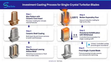
Most turbofan blades are produced through investment casting (lost-wax process). Howmet's manufacturing process illustrates the key steps:
- Create a precise wax pattern matching the blade shape
- Insert engineered ceramic cores to form internal cooling passages
- Coat the wax pattern with ceramic shell material
- Remove wax, leaving a hollow ceramic mold
- Preheat mold and pour molten superalloy
- Control cooling to direct solidification
For single-crystal blades, casting success depends on tight directional-solidification control. Research on DD9 alloy directional solidification reports the critical parameters:
- Superheat temperature: 1,580°C
- Pour temperature: 1,525°C
- Withdrawal rate: 3-5 mm/min (above 5 mm/min increases defect risk)
Held in that window, the crystal grows uniformly along the blade axis and avoids grain boundaries or stray grains that weaken the part.
Precision Machining and Quality Control
After casting, each blade undergoes precision finishing. Research on aeroengine cooling hole manufacturing documents the demanding specifications:
Cooling hole parameters:
- Diameter: approximately 0.3-0.5 mm
- Depth-to-diameter ratio: up to 10:1
- Locations: leading edge, pressure/suction surfaces, tip
Tolerances are just as tight:
- Diameter: 0.10 mm
- Position: 0.10-0.15 mm
- Axis angle: ±1 degree
These holes are typically laser-drilled, though electrical discharge machining (EDM) and electrohydraulic drilling are also used. Each blade may contain hundreds of precisely positioned holes. Any error can compromise cooling effectiveness or structural integrity.
Coordinate measuring machines (CMMs) verify airfoil geometry against design specifications. Complex surface geometry requires hundreds of measurement points to confirm the blade matches its CAD model within micron-level tolerances.
Emerging Manufacturing Technologies
Additive manufacturing (3D printing) is moving from research to production. GE's GE9X engine consolidated more than 300 parts into seven additively manufactured components, including Arcam-printed low-pressure turbine blades made from metal powder. Additive manufacturing enables:
- More complex internal geometries impossible with conventional casting
- Faster design iteration without expensive tooling
- Potential for integrated features that reduce assembly
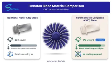
Ceramic matrix composites (CMCs) offer higher temperature capability and lower weight than nickel alloys. GE's F414 turbofan demonstrator completed 500 cycles with rotating CMC low-pressure turbine blades.
Those blades weighed approximately one-third of nickel-alloy equivalents, and second-stage blades needed no air cooling. GE states CMC capability is hundreds of degrees higher than legacy nickel alloys, though commercial high-pressure turbine applications remain under development.
Challenges and Future Trends in Blade Design
Current Design Challenges
Blade design is a set of hard tradeoffs, not a single optimization target:
- Temperature vs. durability: Higher gas temperatures raise efficiency but speed up blade degradation, so each gain needs better materials, more cooling, or shorter service intervals.
- Cooling vs. efficiency: Bleed air from the compressor protects the blade yet taxes engine performance; the goal is minimum cooling flow with full protection.
- Manufacturing cost: Single-crystal casting, precision drilling, and TBC application are expensive, and cost pressure pushes simplification without cutting safety or performance.
- Concurrent failure modes: Research on gas turbine blade defects shows designs must handle several damage mechanisms at once:
- Thermomechanical fatigue from thermal cycling
- Creep under sustained high-temperature stress
- Hot corrosion from fuel contaminants
- Erosion from particulates and foreign object damage
Future Directions
Those same constraints are pushing the next wave of materials, cooling, and design tools.
- Advanced materials: Next-generation single-crystal superalloys with higher refractory content aim at still-higher metal temperatures. Ceramic matrix composites are candidates to replace superalloys in select hot-section roles, cutting weight and cooling demand.
- Cooling innovation: Work centers on more protection from less cooling air—shaped film-cooling holes, additive-made internal lattices, and improved TBCs.
- AI-assisted optimization: Machine learning explores large design spaces faster than manual iteration and surfaces non-intuitive shapes that balance aero, thermal, and structural limits. Paired with rapid cycle simulation, teams can test architecture changes before committing hardware.
- Digital twins: Sensor data plus physics models support condition-based maintenance, so blades are replaced on actual health rather than conservative time limits.
Frequently Asked Questions
How are turbofan blades designed?
Turbofan blade design combines aerodynamic shaping, materials selection, cooling integration, and structural analysis. Engineers use CFD for airfoil profiles, FEA for stress limits, and thermal modeling for cooling networks, then iterate with physical testing. Platforms like SimTurbo help visualize system-level thermodynamic and control interactions.
What are turbofan blades made of?
Modern turbofan blades use nickel-based superalloys with chromium, cobalt, and rhenium. High-temperature blades are often grown as single crystals to eliminate grain boundaries that drive creep and fatigue. Ceramic thermal barrier coatings (typically 7% yttria-stabilized zirconia) add insulation and oxidation resistance.
How are turbofan blades manufactured?
Most turbofan blades are investment cast, with ceramic cores forming internal cooling passages. Single-crystal blades use directional solidification at controlled rates (3–5 mm/min), then laser drilling creates 0.3–0.5 mm cooling holes. Coatings are applied, and CMMs verify geometry to micron-level tolerances.
What is the most efficient turbofan blade design?
Efficiency depends on engine stage, operating conditions, and design priorities. Strong designs usually combine refined airfoils, single-crystal materials, multi-pass internal and film cooling, and tight tip sealing. NASA measured 90% thermodynamic efficiency in the Energy Efficient Engine two-stage high-pressure turbine.
How are turbofan blades cooled?
Blades combine internal convection cooling through serpentine passages with external film cooling from small angled holes. Impingement jets target high-heat zones such as the leading edge. The E3 rotor blade used 2.75% of core airflow for cooling, a meaningful efficiency trade-off.
What role does simulation play in turbofan blade development?
Simulation predicts aerodynamic performance, thermal loads, and structural integrity before costly physical testing. CFD evaluates gas flow, efficiency, and cooling effectiveness; FEA calculates stress, deflection, and vibration. Platforms like SimTurbo help engineers and students visualize thermodynamic interactions and validate control strategies in real time.