Introduction to Micro Axial Flow Turbine Design
Compact, high-efficiency power generation is essential for aerospace and portable power applications. UAV manufacturers need propulsion systems that deliver kilowatts of power within tightly constrained packages.
Emergency backup systems demand rapid startup and portability. Hybrid-electric vehicle developers seek lightweight range extenders that fit into constrained nacelles.
Micro axial flow turbines answer these demands—but they introduce design challenges that conventional turbine engineering rarely encounters. At the 1–100 kW scale, Reynolds numbers drop sharply, tip clearances become proportionally enormous, and manufacturing tolerances rival the blade dimensions themselves. A 0.1 mm surface defect that a large engine would ignore can cost a micro turbine 4 percentage points of efficiency.
Modern simulation platforms like SimTurbo now enable engineers to model thermodynamic cycles, validate compressor-turbine matching, and predict transient startup behavior before committing to physical prototypes. This article explains the architecture, design methodologies, and validation strategies that turn micro-scale constraints into practical, high-performance turbine systems.
Key Takeaways:
- Micro axial turbines run at 1–100 kW and often above 100,000 RPM, where low Re and large tip clearances cut efficiency
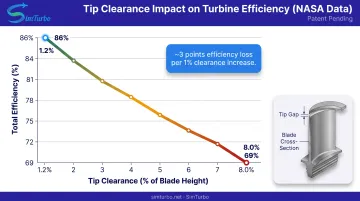
- Low Re (41,000–317,000) costs 7+ efficiency points; tip clearance at 8% of blade height drops efficiency from 86% to 69%
- CFD, cycle tools, and real-time transient models validate performance before manufacturing and cut prototype cost
- Proven in UAV turbojets (230–1,569 N), a 75 kW research blisk, and an 80 kWe hybrid range extender
Fundamentals of Micro Axial Flow Turbine Architecture
Micro axial flow turbines compress and expand gas along a streamwise axis, using alternating rows of rotating blades and stationary vanes to extract energy from high-pressure, high-temperature working fluid. At the 1–100 kW scale, this architecture delivers higher thrust-to-weight ratios than radial turbines when packaging length is less constrained than diameter.
Core Components
Four elements define the machine:
- Rotor blades on a central shaft convert fluid momentum into mechanical work
- Stator vanes upstream or downstream redirect flow to set blade incidence angles
- Housing holds aerodynamic boundaries and structural integrity under thermal and pressure loads
- Shaft assembly transmits torque to a load or compressor and must survive speeds often above 100,000 RPM
Cycle and Configuration Choices
Micro turbines follow the Brayton cycle: inlet air is compressed, heated in a combustor or heat exchanger, expanded through the turbine to produce work, and exhausted. Pressure ratio, turbine inlet temperature, and expansion efficiency set power output and fuel use.
At micro-scale, pressure ratios typically run 1.3–2.0 per stage. Turbine inlet temperature is limited by materials, often 800–1,100°C for nickel superalloys.
Axial designs keep a near-constant radius through the blade row, so stages stack inside a slender nacelle. Radial turbines turn the flow 90 degrees: simpler to build and higher pressure ratio per stage, but more frontal area. Micro UAVs and distributed propulsion usually favor axial layouts when thrust density and a clean nacelle matter more than manufacturing simplicity.
Critical Dimensional Parameters
Three dimensions dominate losses and structural margins at this scale:
- Blade height (typically 5–15 mm): sets annulus area and strongly influences Reynolds number
- Tip clearance (gap from blade tip to casing): hold to 1–2% of blade height; absolute gaps of 0.1–0.2 mm need precision machining
- Chord length (streamwise blade width): drives boundary-layer growth and blade stiffness
As chord and height shrink, surface roughness and clearance become proportionally larger penalties.
Typical Performance Ranges:
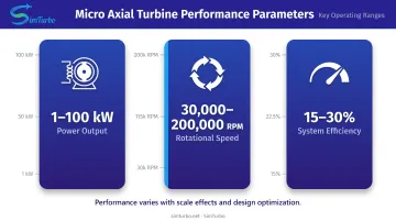
- Power output: 1–100 kW shaft power (or equivalent thrust in propulsion applications)
- Rotational speeds: 100,000–200,000 RPM for smallest configurations; 30,000–100,000 RPM for higher-power designs
- Stage pressure ratio: 1.3–2.0 per axial stage
- Total efficiency: 15–30% for complete micro-turbine systems (lower than 30–40% for megawatt-class engines due to scale effects)
Key Design Challenges at the Micro-Scale
Shrinking an axial turbine does more than scale geometry. Losses, tolerances, materials, and rotordynamics all shift in ways that dominate stage efficiency.
Reynolds Number Effects and Boundary Layer Losses
Reynolds number (proportional to flow velocity and characteristic length, and inversely to kinematic viscosity) governs boundary-layer behavior. Micro turbines operate between 41,000 and 317,000, far below the millions typical of large engines.
NASA testing of a 10 kW axial turbine stage measured total efficiency falling from 0.86 to 0.79 as Reynolds number dropped from 317,000 to 41,000: a 7-percentage-point penalty. Thicker boundary layers raise skin friction, shrink effective flow area, and trigger early separation, cutting stage work and raising exit losses.
Blade Manufacturing Constraints
Minimum blade thickness, surface roughness, and profile accuracy all scale poorly at micro dimensions. NASA's small-axial-rotor study showed how fast geometry errors become aerodynamic loss:
- As-cast trailing edges at 0.053 cm (design: 0.038 cm) produced 16.5% trailing-edge blockage
- Profile deviations of ±0.05 mm beyond drawing tolerances were common
- Polishing suction surfaces and lacquering pressure surfaces cut average roughness from 1.35 to 0.64 μm (~1 point efficiency gain)
- EDM profile correction added about 4 more points of total improvement
Tolerance and finish directly set aerodynamic loss at this scale.
Tip Clearance Challenges
Absolute tip clearances of 0.1–0.5 mm become proportionally huge when blade height is only 5–15 mm. NASA experiments varied clearance from 1.2% to 8.0% of passage height and measured total efficiency dropping from 0.86 to 0.69: roughly 3 points lost per 1-point rise in clearance-to-height ratio.
Leakage bypasses the blade, cutting stage work and raising entropy. Thermal growth widens gaps further, so designers either add active clearance control or accept cold-build clearances that give up efficiency at design conditions.
Material Selection Constraints
Micro-scale blades must survive centrifugal stresses above 200 MPa at 100,000+ RPM and resist oxidation near 1,000°C turbine inlet temperature. Common material tradeoffs:
- Nickel superalloys (such as Inconel 718): high-temperature strength, hard to machine at millimeter scale
- Titanium alloys: lower density and easier machining, limited to ~600°C
- Ceramics / CMCs: high thermal resistance, still brittle and costly
A 2020 micro-axial design study modeled structural steel and found hub stress concentrations. Raising fluid temperature cut predicted fatigue life by 38% at 5 bar, so aero and structural choices stay tightly coupled.
Rotordynamic Challenges
At 100,000+ RPM, rotor critical speeds (natural frequencies where shaft bending resonates) fall inside or near the operating range. Micro shafts are slender and flexible, so bearing placement and damping matter early.
High-speed gas bearings or compliant foil bearings keep friction low but need precise manufacturing and control. Imbalance forces scale with speed squared; even micrograms of mass asymmetry can drive destructive vibration.
An ASME miniature turbojet rotor study accumulated more than 1,000 start-stop cycles on compliant foil journal and thrust bearings. The hardware held up, but it also showed how specialized the bearing stack must be.
Design Methodologies and Aerodynamic Optimization
Velocity Triangle Analysis
Velocity triangles relate blade speed, absolute gas velocity, and relative velocity at inlet and exit. For a given rotational speed and mass flow, designers calculate blade angles (stagger, camber, and twist) that minimize incidence and deviation losses at the design point.
Off-design operation (lower speed or mass flow) alters those triangles, raising incidence and cutting efficiency. Mean-line codes iterate pressure ratio, work coefficient, and flow coefficient to lock in feasible geometry before detailed 3D analysis.
Computational Fluid Dynamics (CFD) Modeling
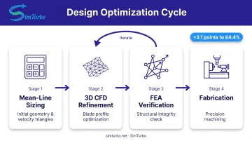
Modern micro-turbine design uses CFD to resolve blade-passage flow, pinpoint loss sources, and refine profiles. A 7 kW micro-axial Brayton turbine study paired Engineering Equation Solver for 1D sizing with ANSYS CFX for 3D simulation, lifting predicted efficiency from 81.3% to about 84.4% through iterative optimization.
Simulation quality hinges on a few practical choices:
- Mesh density at leading and trailing edges
- Turbulence model (k-ω SST is common for transitional boundary layers)
- Convergence criteria tight enough to trust separation and secondary-flow predictions
Engineers still trade compute cost against the need to capture separation, transition, and tip-leakage vortices—the losses that dominate at micro scale.
Blade Profiling Techniques
Low Reynolds numbers force careful airfoil choices. Each geometric lever pulls efficiency and structure in opposite directions:
- Thickness: Supports structural loads but thickens boundary layers and raises blockage
- Camber: Sets turning and diffusion; too much camber triggers separation
- Leading-edge radius: Large enough for incidence tolerance, small enough to limit thickness
- Trailing-edge wedge angle: Controls base pressure and exit blockage
NASA's profile-correction work showed that even sub-millimeter deviations cost efficiency. Precision machining and post-process inspection are not optional at this scale.
Multi-Stage Design Considerations
Stacking stages raises overall pressure ratio, but it also adds interstage loss and mechanical complexity. How you distribute that work matters as much as how many stages you add:
- Front-loaded pressure rise can push the compressor toward surge
- Back-loaded rise can drive material temperatures and stresses past limits
- Work split between stages trades peak efficiency against cost, weight, and part count
A two-stage axial turbine in Brayton Energy's 80 kWe hybrid-electric range extender shows a practical multi-stage layout, though detailed performance data remain proprietary.
Case Study: Optimization-Driven Efficiency Improvement
The same Daabo 2020 7 kW stage shows what a closed design loop can deliver. Starting from mean-line sizing, the team iterated blade stagger, trailing-edge wedge angle, and pressure-side shape in 3D CFD, then checked structural margins with fluid-structure interaction analysis.
That pass improved simulated isentropic efficiency by 3.1 percentage points (to 84.4%) without giving up mechanical integrity. The sequence—mean-line geometry, CFD refinement, FEA verification, then fabrication—is the practical path most micro-axial programs follow before cutting metal.
Performance Analysis and Validation Using Simulation Tools
Key Performance Metrics
Four metrics dominate micro axial-flow turbine evaluation:
- Isentropic efficiency: Actual work extraction versus ideal reversible expansion, isolating aerodynamic quality from boundary conditions
- Power output: Delivered shaft kilowatts or thrust
- Specific fuel consumption: Fuel mass per unit power per unit time
- Pressure ratio: Expansion capability across the stage
At micro-scale, validate each metric against test data. Reynolds number, tip clearance, and surface roughness effects often exceed what simplified models predict.
Simulation Platforms Enable Pre-Prototype Validation
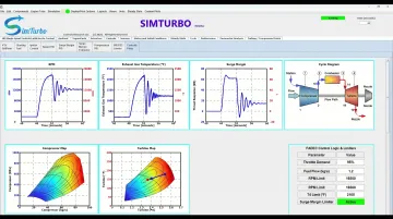
Real-time simulation platforms model full thermodynamic cycles, component matching, and transient behavior before hardware exists. SimTurbo lets engineers build complete engine architectures from configurable components:
- Inlets, compressors, and combustors
- Turbines, nozzles, and shafts
Steady-state runs predict performance maps across altitude, Mach number, and ambient temperature. Transient simulation captures startup dynamics, throttle response, compressor surge margins, and turbine inlet-temperature spikes so you can validate control laws on a desktop PC.
SimTurbo's J85-GE-21 case reached ±2% agreement with NASA Lewis Research Center test data for thrust, mass flow, temperature, and thrust-specific fuel consumption. For micro turbines, you can define component maps, shaft arrangements, and control logic, then export time-series results for post-processing in MATLAB, Python, CSV, or Excel:
- RPM and exhaust-gas temperature
- Thrust and specific fuel consumption
Real-Time Simulation for Control System Development
Micro-scale gas turbines need fast throttle response and tight turbine inlet-temperature control to avoid material failure. Platforms with built-in PID and FADEC (Full Authority Digital Engine Control) logic let you test the following without risking hardware:
- Acceleration schedules and limiter settings
- Sensor-failure responses
- Transient graphs of component maps and cycle diagrams as throttle moves
That shortens control tuning cycles and raises safety before the first engine run.
Applications and Use Cases Across Industries
Micro axial-flow turbines show up wherever compact, high-speed turbomachinery must deliver high power density: UAV propulsion, portable generators, and hybrid-electric range extenders.
Aerospace Applications
UAV propulsion: Manufacturers like AMT Netherlands build turbojet engines with axial-flow turbine stages spanning 230–1,569 N thrust. Models such as the Titan and Lynx pair radial compressors with axial turbine stages and power target drones, tactical reconnaissance UAVs, and subscale testbeds.
Research and education: A 2025 AIAA paper documents a 75 kW single-stage axial turbine blisk for a student-built micro-turbojet. The work combined CFD, FEA, and five-axis CNC machining in aluminum and Inconel 718, giving students hands-on experience with micro-scale gas-turbine design and manufacturing.
Auxiliary power units (APUs): Large-aircraft APUs are mature, but micro APUs for small unmanned platforms are still largely developmental. Few public examples meet the 1–100 kW axial-turbine criteria.
Portable Power Generation
Military and emergency systems: Compact, high-power-density generators can support forward-deployed units and disaster-response teams that need kilowatts without grid access. Verified fielded systems using 1–100 kW axial-flow turbines remain scarce in public literature; most portable military generators still use diesel-reciprocating engines or radial-turbine microturbines.
Off-grid applications: Remote monitoring stations, telecom sites, and field hospitals benefit from lightweight, fuel-flexible turbine generators. Technical viability is clear, though published case studies and market adoption are still limited.
Emerging Hybrid-Electric Propulsion Concepts
Brayton Energy's 80 kWe intercooled-recuperated microturbine uses a two-stage axial turbine as a range extender for Class 5/7 series-hybrid delivery vehicles. The design pairs high power density with lower emissions than diesel equivalents.
Simulation platforms that fold electric motor/generator components into shaft logic—such as SimTurbo's hybrid-electric modeling capability—let engineers optimize power splits, battery sizing, and transient power management before they build prototype powertrains.
Manufacturing Considerations and Quality Control
Precision Manufacturing Methods
Five-axis CNC micro-machining cuts complex blade twist and camber while holding tolerances below ±0.05 mm. The AIAA 75 kW blisk path is typical: aluminum for prototypes, then Inconel 718 for production, each from a single disk.
Wire EDM removes metal until profile traces match design contours. NASA’s small-axial-rotor work recovered about 4 percentage points of efficiency lost to as-cast geometry error. The process suits thin, high-aspect-ratio features in hard superalloys without tool wear.
Metal additive manufacturing (selective laser melting and electron-beam melting) can produce integral blade-disk structures with internal cooling passages. As-built surface finish is often 10–20 μm, so post-processing is required. Published micro-turbine AM cases with tolerances and performance data are still rare.
Casting plus finishing supports low-cost prototypes but needs surface work to meet aero targets. NASA polished suction surfaces and lacquered pressure surfaces on as-cast rotors, cutting roughness from 1.35 to 0.64 μm.
Surface Finish Requirements
When roughness height approaches boundary-layer thickness, skin friction rises quickly. At micro scale, Ra < 0.8 μm matters: NASA data show roughly 1 percentage point efficiency gain from halving roughness.
Common finish routes include:
- Polishing and lapping for controlled Ra on airfoils
- Electrochemical machining for hard alloys without mechanical tool wear
- Coatings where erosion or thermal protection is required
If thermal-barrier coatings are used, build 100–200 μm of coating thickness into the manufacturing tolerance stack.
Inspection and Quality Control Challenges
Optical systems (laser scanners, white-light interferometers) measure blade profiles and finish without touching delicate features. Hub fillets and internal passages are still hard to reach.
CMMs check chord, stagger, and twist. Standard touch probes lose resolution in sub-5 mm passages; micro-CMMs reach sub-micron accuracy but raise cost.
NDT options for micro blades include:
- X-ray CT for internal porosity in AM parts
- Fluorescent penetrant inspection for surface cracks
Published NDT tolerance standards for micro axial-turbine blades are scarce, so teams usually set acceptance criteria program by program.
Frequently Asked Questions
What are micro turbines used for?
Micro turbines generate 1–100 kW for UAV propulsion, portable military and emergency backup, and hybrid-electric range extenders. They beat batteries on power density and fuel cells on refuel speed where compactness and fuel flexibility matter.
How much does a microturbine cost?
Prototype and development costs typically run $10,000 to $100,000+ depending on power output, materials, and application. Custom engineering, precision manufacturing, and low volumes drive price; no public database covers 1–100 kW axial microturbines.
What is the typical efficiency of micro axial flow turbines compared to larger turbines?
Micro axial turbines reach stage isentropic efficiencies of about 79–86% under favorable conditions, but full-system thermal efficiency often falls to 15–30% from Reynolds-number penalties and clearance losses. Megawatt-class engines typically achieve 30–40% thermal efficiency.
What are the primary failure modes in micro turbine designs?
Leading causes include blade fatigue from high-speed rotation, thermal stress cracking from rapid temperature swings, bearing failures (especially oil-free gas or foil bearings), and foreign-object damage. Hub stress concentrations and tip deflections also drive design and inspection requirements.
How do you validate a micro turbine design before manufacturing?
Engineers combine CFD for aerodynamics, cycle tools such as SimTurbo for steady-state and transient behavior, and FEA for structural and thermal checks. Scaled rig testing validates component maps when budget allows; NASA J85-GE-21 results within ±2% show the fidelity possible before hardware build.
What materials are best suited for micro turbine blades?
Nickel-based superalloys such as Inconel 718 dominate high-temperature use (800–1,100°C) for strength and oxidation resistance. Titanium alloys fit lower-temperature (~600°C), weight-sensitive designs. Ceramics and CMCs offer extreme heat capability but stay costly and brittle for most production micro turbines.