The stakes are high: poor combustion control wastes fuel, increases emissions, accelerates equipment wear, and creates safety risks. With an estimated 38,537 conventional industrial boilers operating in the United States alone, even modest efficiency gains translate to substantial cost savings and environmental benefits across the industrial sector.
Key Takeaways
- Combustion control matches firing rate and air-fuel ratio to heat demand; burner management handles safety interlocks and startup/shutdown
- Cross-limiting prevents fuel-rich explosions: air leads fuel on increases, fuel leads air on decreases
- Oxygen trim can improve efficiency up to 2% by holding excess air at ideal levels from real-time flue gas data
- Parallel positioning eliminates jackshaft linkage hysteresis and improves repeatability
- Strong combustion control cuts fuel cost and emissions, extends equipment life, and eases regulatory compliance
What Is a Burner Combustion Control System?
A combustion control system (CCS) consists of the instrumentation and control logic that modulate burner firing rate and maintain proper air-fuel ratios in response to process demand. That demand may be steam pressure in a boiler, hot water temperature, or process heat in an industrial furnace.
The fundamental combustion challenge: Complete combustion requires precise fuel-air mixing. Too little air creates dangerous incomplete combustion, producing carbon monoxide (CO), unburned fuel, smoke, and explosion risk. Too much air wastes energy by heating excess nitrogen that escapes up the stack without contributing to useful heat transfer.
CCS vs. BMS: Understanding the Distinction
The combustion control system focuses on ongoing efficiency and load regulation, continuously adjusting fuel and air flows to match demand. The burner management system (BMS), by contrast, provides safety functions: startup sequences, purge timing, flame monitoring, proof of airflow, and emergency shutdown logic. According to NFPA 87 (2015), a BMS encompasses the field devices, logic system, and final elements dedicated to combustion safety and prevention of equipment misoperation or damage.
Both systems must work in concert. Modern controllers often integrate CCS and BMS functions in a single platform, but their priorities differ: BMS asks "can there be a fire safely?" while CCS asks "how much fire, with what air-fuel ratio?"
The Basic Control Loop
A master controller monitors process demand (steam pressure, temperature, or other process variable) and generates a firing rate signal, typically expressed as 0–100% of capacity. This signal drives both fuel control valves and combustion air dampers in a coordinated fashion to maintain the correct stoichiometric ratio plus desired excess air throughout the firing range.
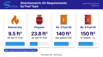
Stoichiometric requirements vary by fuel:
| Fuel | Stoichiometric Air Requirement |
|---|---|
| Natural gas | ~10 ft³ air per ft³ gas |
| Propane | 23.82 ft³ air per ft³ propane |
| No. 2 fuel oil | 180–195 ft³ air per lb fuel |
| No. 6 fuel oil | 170–185 ft³ air per lb fuel |
In practice, burners operate with 10–15% excess air (or 2–4% O₂ in flue gas) to ensure complete combustion despite variations in fuel quality, ambient conditions, and burner wear.
How Combustion Control Systems Work
Master Control and PID Loops
Every CCS relies on a proportional-integral-derivative (PID) controller that monitors the process variable (steam pressure or temperature) and generates corrective signals to maintain setpoint. Controllers such as the Fireye PPC6000 provide dual independent PID loops for redundancy.
The master controller's output, a firing rate demand from 0–100%, is transmitted to both fuel valves and air dampers, which must move in a coordinated fashion to preserve safe air-fuel ratios across the entire load range.
Characterization Curves
The relationship between firing rate percentage and required fuel or air flow is rarely linear. Burners have unique flow characteristics shaped by valve design, damper geometry, and combustion aerodynamics. Systems handle this with characterization curves: lookup tables with multiple coordinate pairs (typically 10–24 points) that translate firing rate percentage to actual valve or damper positions.
For example, the Fireye PPC6000 supports up to 24 curve points per fuel profile with positioning precision of ±0.1 degree, while the Siemens LMV5 uses up to 15 points. The controller interpolates between defined points to achieve smooth modulation.
Position Feedback and Verification
Modern systems continuously monitor actual valve and damper positions, comparing commanded positions to feedback signals. This closed-loop verification detects:
- Sticking or sluggish actuators
- Mechanical failures
- Linkage slippage (in jackshaft systems)
- Air supply interruptions
When actual position deviates significantly from commanded position, the controller can trigger alarms or safety shutdowns before unsafe air-fuel imbalances develop.
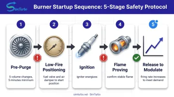
Purge-to-Light-Off-to-Modulation Sequence
Before ignition, the system must purge the firebox to clear any accumulated fuel vapors. FM Global DS 6-5 specifies at least five boiler-enclosure volume changes, at least five continuous minutes, and purge airflow of at least 25% of full-load volumetric flow for covered multiple-burner oil- and gas-fired boilers.
After successful purge:
- Low-fire positioning – Fuel valve and air damper move to low-fire start positions
- Ignition and flame proving – Igniter energizes and flame scanner confirms stable flame
- Release to modulate – Control system permits firing rate to increase to meet demand
Digital vs. Analog Control
Digital control systems, whether PLC-based or dedicated combustion controllers, have largely replaced older analog relay and pneumatic systems. Digital platforms offer:
- Repeatable, software-defined characterization curves
- Data logging for efficiency analysis and compliance reporting
- Remote diagnostics and parameter adjustment
- Integration with plant-wide SCADA or DCS networks
- Predictive maintenance alerts based on actuator performance trends
Types of Combustion Control Systems
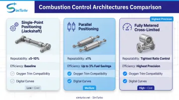
Three main architectures dominate burner combustion control, from simple mechanical linkage to fully metered electronic systems. Precision, efficiency, and cost scale together as you move up the list.
Single-Point Positioning (Jackshaft)
Single-point systems use one actuator driving both fuel valve and air damper through mechanical linkage—typically a crank arm and jackshaft arrangement. This oldest, simplest approach still appears on smaller and legacy boilers.
Limitations:
- Mechanical hysteresis ("slop" in linkage) requires extra excess air for safety margin
- Poor repeatability between increasing and decreasing firing rates
- Seasonal retuning needed as ambient temperature affects linkage expansion
- Mechanical wear over time degrades performance
Parallel Positioning (Linkage-Less)
Parallel positioning systems use separate actuators for fuel valve and air damper, eliminating mechanical linkage and enabling independent position control with electronic cross-limiting.
Advantages:
- Improves repeatability to ±1% vs. ±5–10% for jackshaft
- Enables lower excess-air operation for better efficiency
- Supports oxygen trim optimization
- Allows digital characterization curves adjusted in software
- Meets low-NOx burner control requirements
Cleaver-Brooks reports up to 3% fuel-cost savings from upgrading jackshaft systems to parallel positioning by eliminating hysteresis and enabling tighter air-fuel ratio control.
Fully Metered Cross-Limited
Fully metered systems use mass-flow transmitters (pressure and temperature compensated) to directly measure fuel and air flows. That yields the most precise air-fuel ratio control; these systems are typically PLC-based because of the computational load.
Key features:
- Flow signals serve as primary feedback; position signals provide error-checking
- Lead-lag logic: air leads fuel on load increases; fuel leads air on load decreases
- Real-time flow measurement corrects for fuel heating value, ambient temperature, and humidity
- Delivers the tightest ratio control for efficiency and safety on large or critical units
Key Control Strategies for Optimal Performance
Three strategies keep combustion safe and efficient as load changes: cross-limiting, oxygen trim, and excess-air management.
Cross-Limiting Control
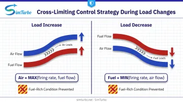
Cross-limiting logic prevents dangerous fuel-rich conditions by enforcing safe sequencing during load changes:
- On firing rate increases: Air setpoint equals the greater of (1) master firing rate signal or (2) actual fuel flow percentage, forcing air to lead
- On firing rate decreases: Fuel setpoint equals the lesser of (1) master firing rate signal or (2) actual air flow percentage, forcing fuel to lead
Why it matters: If air supply fails or lags during a load increase, fuel cannot increase beyond current air flow. If fuel supply fails or lags during a decrease, air cannot drop below current fuel flow. This prevents explosive fuel-air mixtures that could develop during transients.
Oxygen Trim Optimization
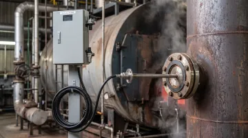
Oxygen trim uses a flue gas O₂ analyzer—typically a zirconium oxide sensor—to measure excess air in real time. Target values are 3–4% O₂ at high fire (compared to 21% in ambient air).
The O₂ PID loop output (limited to ±10–20% adjustment range) multiplies the air flow setpoint, continuously correcting for:
- Variations in fuel heating value (especially with natural gas from different sources)
- Ambient air temperature and humidity changes
- Burner wear, fouling, or component degradation
Calibration and maintenance:
The Emerson Rosemount 6888C analyzer offers accuracy of ±0.75% of reading or ±0.05% O₂, whichever is greater. Automatic-calibration hardware and diagnostics flag when calibration checks are recommended. Proper installation in the flue gas stream is critical to obtaining representative measurements.
Fuel savings: Cleaver-Brooks reports up to 2% efficiency improvement from oxygen trim optimization. The DOE notes that about 1 percentage point of boiler-efficiency improvement is possible for each 15-percentage-point reduction in excess air, subject to maintaining complete combustion.
Excess Air Management
The "sweet spot" for excess air balances two competing losses:
- Too little excess air → Incomplete combustion → High CO, smoke, unburned fuel, safety risk
- Too much excess air → Stack losses → Energy wasted heating nitrogen that contributes no heat transfer
Optimal excess air varies by load:
- Most burners need higher excess air at low fire for flame stability and adequate mixing
- At high fire, improved mixing energy and residence time allow leaner operation (lower excess air)
DOE guidance suggests 10% excess air is attainable on well-designed natural-gas-fired systems, though this target varies by fuel, burner design, and load.
Safety Features and Burner Management Systems
CCS vs. BMS: Safety Functions
The burner management system provides independent safety functions, separate from efficiency optimization:
- Flame detection – Continuous monitoring via UV or flame-rod scanner; fuel shutoff on flame failure
- Purge timing – Enforces minimum purge duration and airflow before ignition attempts
- Proof of air flow – Verifies adequate combustion air before fuel is admitted
- Fuel pressure limits – High and low gas-pressure switches prevent operation outside safe ranges
- High temperature limits – Protects against overheating or tube failure
FM Global DS 6-5 requires proof of closed safety shutoff valves, purge-position dampers, running fans, satisfactory drum level, and normal fuel conditions before purge begins. On total flame loss, the system must trip all fuel and run a complete purge before restart.
Proactive Safety Controls
Modern systems stop unsafe conditions before they escalate:
- Cross-limiting prevents fuel-air imbalances during load changes
- Position monitoring catches actuator failures immediately
- BMS–CCS communication confirms both systems agree on burner state before operation
- Safety trips require manual operator reset and a full purge before restart
Benefits of Modern Combustion Control Systems
Efficiency and Cost Savings
Quantified fuel savings:
- Upgrading from jackshaft to parallel positioning: up to 3% fuel-cost savings
- Adding oxygen trim: up to 2% additional efficiency improvement
For a mid-sized industrial boiler operating 6,000 hours per year, even a 3% fuel savings can translate to tens of thousands of dollars annually, with payback periods often under two years.
Emissions Reduction
Precise air-fuel ratio control cuts carbon monoxide (CO) from fuel-rich operation and nitrogen oxides (NOx) from excess oxygen and high flame temperatures.
Facilities can often meet EPA and state air quality regulations through improved combustion control alone, deferring or avoiding hardware modifications like low-NOx burners or selective catalytic reduction (SCR) systems.
Regulatory Compliance
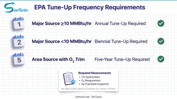
EPA Boiler MACT regulations require periodic tune-ups. Those tune-ups cover burner and air-to-fuel-ratio control inspection, CO optimization, and CO and O₂ measurement before and after adjustments.
Tune-up frequency varies by source category, capacity, and equipment:
- Major-source boilers ≥10 MMBtu/hr: annual tune-ups
- Major-source boilers <10 MMBtu/hr: biennial tune-ups
- Area-source boilers with continuous oxygen trim: five-year tune-up intervals (where biennial would otherwise apply)
Modern CCS platforms provide data logging and reporting that simplify compliance documentation.
Operational Benefits
- Replace wear-prone mechanical linkage with electronic actuators to cut maintenance
- Hold tighter steam pressure or temperature bands for steadier process control
- Use data logging to speed troubleshooting and support predictive maintenance
- Connect to plant energy management and SCADA systems for plant-wide visibility
Frequently Asked Questions
What is a combustion control system?
A combustion control system (CCS) is the instrumentation and control logic that adjusts fuel and air flow rates to meet heat demand. It holds safe, efficient air-fuel ratios across the firing range, from low fire to high fire.
What is a burner management system (BMS)?
A burner management system (BMS) is the safety system that manages burner startup sequences, monitors flame status, and enforces purge requirements. It shuts the burner down automatically if unsafe conditions occur, such as flame failure or loss of airflow.
What is the difference between a BMS and a CCS?
The BMS focuses on safety (can there be a fire safely?) while the CCS focuses on efficiency and control (how much fire, with what air-fuel ratio?). Both must work together, and modern integrated controllers often combine both functions in a single platform with clear separation of safety-critical and efficiency-optimization logic.
How does cross-limiting work in combustion control?
Cross-limiting ensures air leads fuel on firing rate increases and fuel leads air on decreases. The controller compares actual flow or position to demand and always chooses the safer path, so air never lags fuel on a load increase and fuel never lags air on a decrease. That prevents dangerous fuel-rich mixtures during transients.
What is oxygen trim and why is it important?
Oxygen trim is a feedback loop that uses flue gas oxygen measurement to fine-tune excess air in real-time. It corrects for variations in fuel heating value, ambient temperature, humidity, and burner condition, maximizing efficiency while maintaining safe, complete combustion. Oxygen trim can improve efficiency by up to 2% and reduce tune-up frequency under EPA regulations.
How much can combustion control upgrades save on fuel costs?
Upgrading from jackshaft to parallel positioning systems can save up to 3% in fuel costs by eliminating mechanical hysteresis and enabling tighter air-fuel ratio control. Adding oxygen trim can provide an additional efficiency improvement of up to 2%. Payback periods typically range from one to three years, depending on fuel costs, boiler size, and annual operating hours.